
اختبارات السلامة الكهربائية (Electrical Safety Testing)
Electrical Safety Testing |
بقلم Frank Weithöner
by Frank Weithöner |
يضمن مصنّعو الأجهزة الطبية الالتزام بكل أنظمة السلامة في التصميم والتصنيع، وأن الجهاز خرج آمناً. أما الآن فمهمة المستشفى (ورشته الفنية) هي ضمان بقاء الجهاز آمناً أثناء الاستخدام. وفي العالم المتقدم تكون اختبارات السلامة الكهربائية إلزامية بعد كل إصلاح لجهاز طبي، وهي كذلك جزء من إجراءات الصيانة الوقائية (PPM). Manufacturers of medical equipment ensure that all safety regulations during the design and manufacture are complied with and a safe equipment has been produced. Now it is the task of the hospital (hospital workshop) to ensure that the equipment remains safe during usage. In the developed world electrical safety tests are compulsory after every repair of a medical equipment and are furthermore, part of the preventive maintenance procedure (PPM).
وضعت منظمات وطنية ودولية مثل ANSI وBSI وEEC وIEC وISO وNETA وNFPA معايير سلامة وإجراءات اختبار. وللأجهزة الطبية يُعدّ المعيار IEC 62353 المعيار الأكثر تطبيقاً. National and international organisations like ANSI, BSI, EEC, IEC, ISO, NETA, NFPA have defined safety standards and test procedures. For medical equipment IEC 62353 is the most widely applied testing standard.
الوضع في البلدان النامية: لا تكاد معايير السلامة المذكورة تُطبَّق في البلدان النامية، ولذلك أسباب مختلفة: عدم وجود جهات رقابية، وعدم إدراك إدارة المستشفى لأهمية اختبارات السلامة، وعدم توفر الوقت أو المال للقسم التقني، وعدم معرفة الفنيين كيفية إجراء الاختبارات أو اعتراضهم بعدم توفر أجهزة القياس الخاصة المطلوبة.
Situation in developing countries
In developing countries the above mentioned safety standards are hardly applied. There are different reasons for this: Monitoring organisations do not exist, the hospital management is not aware of the importance of safety tests, the technical department has no time or money to implement safety tests, and the technicians do not know how to perform the tests or they point out that the needed special measurement equipment is not available.والأمر لا يجب أن يكون هكذا؛ فاختبارات السلامة الكهربائية ليست صعبة الإجراء وأجهزة الاختبار الخاصة ليست لازمة فعلاً. ( This does not have to be the situation: Electrical safety tests are not difficult to perform and special test equipment is not really needed. (↓ أجهزة الاختبار↓Test equipment)
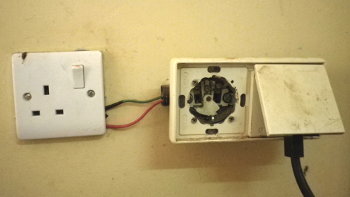 لكن من المهم أيضاً إدراك أن التحديات في البلدان النامية مختلفة؛ فلماذا يُجري الفني اختبارات سلامة على جهاز طبي والتركيب الكهربائي في المستشفى معطوب، والمصاهر وقواطع RCD غائبة، ومقابس الحائط مكسورة، وقوابس الطاقة مفقودة — كل هذا لا يجعل المستشفى أكثر أمناً. لذلك يجب أن تغطي اختبارات السلامة الكهربائية في البلدان النامية (وبخاصة) فحص محيط الجهاز لا الجهاز نفسه فقط.
But, it is also important to understand that the challenges in developing countries are different. For example: Why should a technicians perform safety tests
on medical equipment while the electrical installation in the hospital is faulty, fuses and RCDs are missing, wall sockets are broken and power plugs
are missing do not make the hospital safer? Electrical safety tests in developing countries should therefore, (and particularly) cover checking the
environment of the equipment and not only the equipment itself.
الفحص البصري: يجب أن يبدأ كل اختبار سلامة بفحص بصري للجهاز وتغذيته، وفي البلدان منخفضة الدخل هذا أهم جزء في اختبار السلامة الكهربائية لأن معظم الأضرار الخطرة مرئية ولا تحتاج قياسات معقدة.
Visual inspection
Every safety test should start with a visual check of the equipment and its power supply. Especially in low-income countries this is the most important part of an electrical safety test because most of the dangerous damages are visible and do not need complex measurements.فحص بصري بسيط A simple من الخارجvisual inspection from the outsideللجهاز يجب أن يشمل: of the equipment should cover:
 مقبس الحائط. The wall socket.
هل مقبس الحائط سليم أم تالف؟ Is the wall socket in good working order or is it damaged?
قابس الطاقة. The power plug.هل القابس سليم ومن النظام الصحيح؟ Is the power plug OK and of the correct system?
هل الملامسات نظيفة أم متفحمة؟ Are the contacts clean or are they charred?
كبل الطاقة. The power cable.هل كبل الطاقة تالف؟ الكبلات الهشة والمرقّعة يجب تغييرها. Is the power cable damaged? Brittle and patched power cables have to be replaced.
مثبّت الشد (strain relief). The strain relief.اسحب الكبل: هل مثبّت الشد محكم؟ افحص الجانبين، على الجهاز وعلى Pull the cable. Is the strain relief tight? Check on both sides, on the equipment and on
القابس. ( the plug. (How to connect a mains plug)
فحص بصري بسيط A simple فحص بصري بسيط للداخلvisual inspection of the insideللجهاز: of the equipment:
هل تُظهر الجهاز علامات فرط حرارة واحتراق؟ Does the equipment show signs of overheating and burns?هل كل توصيلات الكبلات محكمة؟ انتبه للكبلات المفكوكة. Are all cable connections tight? Look out for loose cables.هل توجد أسلاك عارية؟ Are there any bare wires?هل المصاهر صحيحة؟ المصاهر المجسّرة يجب إزالتها في الحال. Are the fuses correct? Bypassed fuses have to be removed immediately. أجهزة الاختبار: لأن اختبارات السلامة للأجهزة الطبية تستغرق وقتاً طويلاً غالباً، فإن كل ورش المستشفيات في العالم المتقدم تملك جهاز اختبار سلامة كهربائية آلياً (safety analyser). وهذه الأجهزة متعددة الوظائف وتُجري كل الاختبارات آلياً دون تغيير إعدادات أو توصيلات، وتُطبع نتائجها بعد ذلك، ولا يحتاج الفني حتى إلى معرفة كيف تُجرى الاختبارات أو ما حدود القيم. وهذا عملي جداً ويوفر الوقت، لكن هذه الأجهزة غالية أيضاً ولذلك تكاد تكون معدومة في ورش المستشفيات في البلدان النامية.
Test equipment
Since safety tests for medical equipment are often time-consuming all hospital workshops in the developed world have automated electrical safety tester (safety analyser). These tester are multiple function tester and they carry out all tests automatically, no settings and connections have to be changed. The test results are printed out afterwards. The technician does not even have to know how the tests are performed or what the value limits are. This is very handy and time-saving. But these analyser are also expensive and thus almost non-existent in hospital workshops in developing countries.لكن الاختبارات المختلفة يمكن إجراؤها يدوياً — وحتى دون أجهزة قياس خاصة؛ فلا نحتاج إلا معرفة الاختبارات المطلوبة وكيفية إجرائها وما حدود القيم المسموح بها، وللقياس لا نحتاج إلا مقياساً رقمياً عادياً. But the different tests can still be carried out manually - even without special measurement equipment. We only have to know what tests should be done, how they are carried out and how high the limit values are allowed to be. And for measuring we only need a common digital multimeter.
إجراءات الاختبار: تُشرح فيما يلي أصناف الأجهزة وأنواعها، وهذا مهم لأن إجراءات الاختبار ونتائجه تعتمد على هذا التصنيف. ثم تُوصف اختبارات السلامة الكهربائية المختلفة وطرائقها مع حدود القيم. وبعد إجراء الاختبار تُقارن القيمة المقاسة بالحد، فإن كان الجهاز داخل الحد فقد نجح في الاختبار. ويُدوَّن نتيجة الاختبار في تقرير أو بطاقة عمل، ثم يُنتقل إلى الاختبار التالي.
Test procedures
In the following the different equipment classes and types are explained. This is important because test procedures and test results depend on the this identification. Then the different electrical safety tests and test methods are described. Here also the limit values are given. After performing a test the measured value has to be compared with the limit value. Is an equipment within the limit value it has passed the test. The test result should be written down in a test report or job card. Then the next test can be carried out.الإجراءات المقدمة مناسبة خصوصاً لورش المستشفيات في البلدان منخفضة الدخل؛ فالاختبارات سهلة الإجراء وتعطي نتائج موثوقة ولا تحتاج محلل سلامة غالياً. The introduced test procedures are particularly suitable for hospital workshops in low-income countries. The tests are easy to carry out, provide reliable results and no expensive safety analyser is needed.
يرجى الانتباه إلى أن إجراءات الاختبار المقترحة لا تغطي كل جوانب السلامة، فقد يكون أحد الاختبارات ناقصاً؛ ومع ذلك فأي اختبار، حتى الأبسط، أفضل من لا شيء. Please note, that the suggested test procedures do not cover every safety aspect. One or the other test might be missing. But nevertheless, any test, even the simplest is better than no test.
أصناف الأجهزة وأنواعها: تُقسم كل الأجهزة الكهربائية إلى أصناف مختلفة حسب طريقة الحماية من الصعقة الكهربائية، وقد تكون الحماية باستخدام أرضي حام أو عزل مزدوج أو تغذية منفصلة.
Appliance classes and types
All electrical equipment are divided in different appliance classes depending on the method of protection against electric shock. The protection can consist of the usage of a protective earth, a double insulation or a separate power supply.قبل اختبار سلامة أي جهاز يجب تحديد صنفه. ولتسهيل التصنيف لكل صنف رمزه الخاص الذي ينبغي أن يوجد على لوحة بيانات الجهاز. Before an equipment can be tested for its safety the appliance class has to be determined. In order to simplify the identification each class has its own symbol which should be found on the rating plate of the equipment.
وللأجهزة الطبية هذا التصنيف لا يكفي، لأن جهازين من الصنف نفسه قد يُصنع أحدهما للاستخدام دون اتصال بالمريض، والآخر للاتصال بجلد المريض، وثالث للاتصال بجسم المريض المفتوح. وتُعبَّر هذه الدرجات المختلفة بنوع الجهاز. For medical equipment this classification is not sufficient enough because a medical equipment of the same class can be made for the usage without a connection to a patient, with a connection to the patient's skin or for a connection to the opened body of a patient. These different degrees are expressed by the appliance type.
الصنف IClass I
جهاز الصنف I له اتصال أرضي حام (PE) موصول بكل الأجزاء المعدنية المكشوفة وبخاصة الهيكل المعدني؛ ولذلك يكون كبل تغذيته ثلاثي الأوعية والقابس بثلاثة أطراف. A Class I equipment has a protective earth connection (PE). This earth connection is connected to all exposed metal parts, especially to the metal housing. The connected power cable is thus a three core mains cable and the power plug has three pins.
 يُحمى المستخدم بعزل أساسي وبالاتصال الأرضي الحام. وفي حالة عطل يلامس فيه الطور الغلاف المعدني يُقصَر تيار العطل إلى الأرضي فيمر تيار قصر كبير وينصهر المصهر داخل الجهاز أو يفصل القاطع الآلي (MCB) في لوحة التوزيع.
The user is protected by a basic insulation and the protective earth connection. In the event of a fault when line comes in contact with the metal
enclosure the fault current is shortened to ground, a big short-circuit current flows and the fuse inside the equipment blows or the circuit breaker
(MCB) in the distribution board gets tripped.
يفضل أن تُحمى الأجهزة الطبية إضافةً بمصهرين داخليين: واحد لمسار الطور وواحد للحيادي. ففي دول كثيرة لا يُعرَّف L وN ويمكن إدخال القابس في المقبس بأي جهة، فيصبح مصهر الحيادي — العديم الفائدة نظرياً — هو مصهر الطور المهم. وكذلك فإن المصاهر الأصغر داخل الجهاز تنصهر أسرع من القاطع الآلي المصنوع لتيارات أعلى. Medical equipment should be additionally protected by two internal fuses, one for the line path and one for neutral. In many countries L and N are not defined and the power plug can be inserted into the wall socket in both ways. Then the neutral fuse which is theoretically useless becomes the important line fuse. Also, smaller fuses inside the equipment blow faster than a MCB which is made for higher currents.
 رمز الصنف I هو إشارة الأرضي في دائرة، وينبغي أن تُطبع على لوحة البيانات، لكن استخدام هذا الرمز غير إلزامي؛ فأجهزة كثيرة بلا رمز، وتُعدّ حينها من الصنف I.
The symbol for Class I equipment is the earth sign in a circle which should be imaged on the rating plate. But the use of this symbol is not mandatory.
Many equipment have no symbol. Then it can be considered as Class I.
الصنف IIClass II
جهاز الصنف II معزول عزلاً مزدوجاً وغير موصول بالأرضي؛ فالسلامة تتحقق بطبقتين (أو أكثر) من مادة عازلة بين الأجزاء الحية والمستخدم، ولا حاجة للتأريض. A Class II equipment is double insulated and not earthed. Safety is achieved by two (or more) layers of insulating material between live parts and the user. Earthing is not necessary.
وإذا تلف عزل واحد منع الثاني أن يصبح أي جزء خارجي تحت الجهد. In case of a damage of one insulation the second prevents any external parts from becoming alive.
يُوصل جهاز الصنف II عادةً بقابس/كبل ثنائي الأطراف بالشبكة، لكن يمكن استخدام توصيل ثلاثي أيضاً؛ وفي هذه الحالة يجب ألا يُوصل PE بالهيكل المعدني للجهاز. وعادةً يكون لجهاز الصنف II مصهر داخلي واحد. The Class II equipment is usually connected with a 2-pin plug/cable to mains. But also 3-pin connections can be used. In this case PE must not connected to the metal housing of the equipment. Class II equipment usually have only one internal fuse.

رمز الصنف II هو الصندوق المزدوج، وينبغي أن يُطبع على لوحة البيانات. The symbol for Class II equipment is the double box which should be imaged on the rating plate.
الصنف IIIClass III
جهاز الصنف III جهاز جهد منخفض؛ فالجهد منخفض جداً (جهد سلامة منخفض جداً — SELV) بحيث لا يصاب من يلامسه بصعقة. A Class III equipment is a low-voltage equipment. The voltage is so low (Safety Extra Low Voltage, SELV) that a person who gets in contact with it does not get an electric shock.
يعمل الجهاز على البطارية أو على تغذية خارجية تعطي جهداً أقل من 50 VAC. ويُجرى اختبار جهاز الصنف III مع اختبار وحدة تغذيته في الصنف I أو II. The equipment runs either on battery or on an external power supply which creates a supply voltage of less than 50 VAC. The testing of Class III equipment is done in conjunction with the power supply tested in Class I or Class II.

رمز الصنف III هو الرقم الروماني III داخل معيّن، وينبغي أن يُطبع على لوحة البيانات. The symbol for Class II equipment is the Roman III inside a rhombus which should be imaged on the rating plate.
محوّل العزلIsolation transformer
استخدام محوّل العزل غير محدد في صنف سلامة إضافي، لكنه إمكانية أخرى للحماية؛ فهو محوّل 1:1 يوفر عزلاً غالفانياً بين كمون الطور والأرضي. وجهد الخرج لا يوجد إلا بين طرفي الخرج ولم يبق بين أحدهما والأرضي. ومقبس الخرج بلا اتصال PE ولا يجوز استخدامه إلا لجهاز واحد. The use of an isolation transformer is not specified in an extra safety class but it is a another possibility of protection. The isolation transformer is a 1:1 transformer which provides a galvanic isolation from line potential to earth. The output voltage is only present between the two output connectors and no longer from one (line) to ground. The output socket has no PE connection and may only be used for one equipment.
يُستخدم محوّل العزل لأجهزة خاصة في غرفة العمليات وفي الورشة، ويجب في الورشة استخدامه دائماً خاصة عند العمل على أجهزة تحت الجهد (مثل وحدات التغذية التبديلية). The isolation transformer is used for special equipment in the operating room and in the workshop. Especially in the workshop the isolation transformer should be always used when working on energised equipment (e.g. switched mode power supplies).

رمز المحوّل يوجد أيضاً على وحدات التغذية الخارجية التي تحتوي محوّلاً. The symbol for a transformer is also find on external power supplies when they contain a transformer.
الأنواع: تحدد أصناف الأجهزة طريقة الحماية من الصعقة، وهذا كافٍ للأجهزة المنزلية لا للأجهزة الطبية.
Types
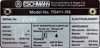
The equipment classes define the method of protection against electric shock. For household appliances this is good enough but not for medical equipment.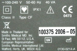 فجهاز طبي من صنف واحد قد يُستخدم دون اتصال بجسم الإنسان (مثل مضخة شفط)، أو باتصال بالمريض (مثل مقياس تشبع الأكسجين)، أو داخل جسم المريض (مثل وحدة الجراحة الكهربائية). ولهذا تُقسم أصناف الأجهزة مرة أخرى إلى أنواع تحدد درجة الحماية.
A medical equipment of one class can be used without a connection to a human body (e.g. suction pump), with a patient connection (e.g. pulse oximeter)
and inside the body of a patient (e.g. electrosurgery unit). That is why the appliance classes are again divided in different types. The types define
the degree of protection.
ولهذا نجد على لوحات بيانات الأجهزة الطبية رمزين: واحد لطريقة الحماية (الصنف) وواحد لدرجة الحماية (النوع). For this reason we find two symbols on the rating plates of medical equipment, one for the method of protection (class) and one for the degree of protection (type).
النوع BType B
مع أجهزة طبية من الأصناف I وII وIII. In combination with medical equipment of Class I, II, III.
 درجة الحماية القياسية من الصعقة، بلا اتصال كهربائي بالمريض، وقد يُوصل الجهاز بالأرضي. وتوصيلات المريض غير موصلة ويمكن فصلها عن المريض فوراً. وتُطلب القيم القياسية لتيارات التسريب المسموحة المذكورة تحت إجراء الاختبار المعني.
Standard degree of protection against electric shock. No electrical contact with a patient. Equipment may be connected to earth. Patient connections
are not conductive and can be immediately released from the patient. Standard values for permitted leakage currents are demanded which are stated
under the respective test procedure.
النوع BFType BF
مع أجهزة طبية من الأصناف I وII وIII. In combination with medical equipment of Class I, II, III.
 الجهاز آمن للاتصال الكهربائي بالمريض لا بالقلب مباشرة. وجزء المريض في الجهاز معزول (دارة عائمة) ويجب فصله عن الأرضي. وتُطلب القيم القياسية لتيارات التسريب المسموحة المذكورة تحت إجراء الاختبار المعني.
Equipment is safe for electrical connection to the patient but not directly to the heart. The patient part of the equipment is isolated (floating
circuit) and has to be separated from earth. Standard values for permitted leakage currents are demanded which are stated under the respective test
procedure.
 وإذا كان الجهاز صالحاً للاستخدام مع مزيل الرجفان وجب طبع هذا الرمز على لوحة البيانات، ومعناه مقاوم للرجفان (defibrillation-proof).
When the equipment can be used in combination with a defibrillator this symbol has to be printed on the rating plate. It means defibrillation-proof.
النوع CFType CF
مع أجهزة طبية من الأصناف I وII وIII. In combination with medical equipment of Class I, II, III.
 يوفر الجهاز أعلى درجة حماية من الصعقة، وهو آمن للاتصال الكهربائي بقلب المريض. وجزء المريض معزول أيضاً (دارة عائمة) ومفصول عن الأرضي كالنوع BF، لكن تيار التسريب المسموح أقل بكثير مما في النوعين B وBF، وتُذكر القيم تحت إجراء الاختبار المعني.
Equipment provides highest degree of protection against electric shock. It is safe for electrical connection to the heart of the patient. The patient part of the equipment is also isolated (floating circuit) and is separated from earth like BF.
The permitted leakage current is much lower than for type B and BF. The values are stated under the respective test procedure.
 وإذا كان الجهاز صالحاً للاستخدام مع مزيل الرجفان وجب طبع هذا الرمز على لوحة البيانات، ومعناه مقاوم للرجفان (defibrillation-proof).
When the equipment can be used in combination with a defibrillator this symbol has to be printed on the rating plate. It means defibrillation-proof.
إجراءات اختبار السلامة الكهربائية: الاختبارات التالية خاصة بالأجهزة الطبية، ولا تتناول اختبارات التركيب الكهربائي وبخاصة الأرضي؛ فتلك تحتاج معرفة أعمق وأجهزة خاصة وينبغي ألا يجريها إلا كهربائيون خبراء.
Electrical safety test procedures
The following tests are electrical safety tests for medical equipment. Tests on the electrical installation especially earthing are not considered. These tests need further knowledge, special test equipment and should be carried out by experienced electricians only.بعد الاختبار يجب توثيق كل النتائج في تقرير، ويُوضع على الجهاز المختبر ملصق يظهر للمستخدم أن الجهاز آمن وتاريخ الاختبار التالي. After testing all test results should be documented on a test report. Tested equipment should get a sticker which shows the user that the equipment is safe and the date of the next test.
والجهاز الذي تتجاوز نتيجته حد القيمة لا يجوز استخدامه مجدداً حتى يُصلح العطل. An equipment with a results beyond the value limit must not be used again until the fault has been rectified.
وتُوصف اختبارات السلامة الكهربائية هذه فيما يلي: These electrical safety tests are described in the following:
اختبار استمرارية الأرضي الحام (1.) Protective earth continuity test (1.)اختبار مقاومة العزل (2.a) Insulation resistance test (2.a)اختبار تيار تسريب الأرضي (3.a) Earth leakage current test (3.a)اختبار تيار اللمس / تسريب الغلاف (3.b) Touch current / Enclosure leakage current test (3.b)اختبار تيار تسريب المريض (3.c) Patient leakage current test (3.c)1. اختبار استمرارية الأرضي الحام (الصنف I): في هذا الاختبار تُقاس مقاومة موصل PE بين اتصال PE في قابس الشبكة والهيكل المعدني غير المطلي للجهاز. وهذا أهم اختبار، وينبغي أن نبدأ به دائماً؛ فإذا فشل الجهاز فيه فسيفشل في الاختبارات الأخرى أيضاً.
1. Protective earth continuity test (Class I)
With this test the resistance of the PE conductor is measured between the PE connection of the mains plug and the unpainted metal housing of the equipment. This is the most important test and we should always start safety tests with this one. If an equipment fails this test it will also fail the other tests.وفق أدلة كثيرة يجب إجراء هذا الاختبار بمحلل سلامة أو جهاز اختبار PAT يطبّق تياراً متردداً 50 Hz على اتصال PE. ولاختبار المعدات الكهربائية (المحركات مثلاً) يُطلب تيار اختبار 10 A أو حتى 20 A لمدة 5 ثوانٍ على الأقل. ولأن هذا التيار قد يكون مرتفعاً جداً لكثير من الأجهزة الإلكترونية والطبية تقترح معايير أخرى تيار اختبار 1 A أو 200 mA فقط. According to many guidelines this test should be done with a safety analyser or PAT tester. The analyser applies a 50 Hz AC-current to the PE connection. For testing electrical equipment (e.g. motors) a test current of 10 A or even 20 A for at least 5 seconds is demanded. Since this current can be much too high for many electronic and medical equipment other standards suggest a test current of 1 A or even only 200 mA.
ولهذا لا حرج في اختبار استمرارية الأرضي الحام للجهاز الطبي بأوميتر؛ فظروف القياس ليست مثالية، لكن الأوميتر من ناحية أخرى لا يُلحق ضرراً بالجهاز. For this reason there is nothing wrong testing the protective earth continuity of medical equipment with an ohmmeter. The measurement conditions are not perfect but on the other hand the ohmmeter does not do any damage to the medical equipment.
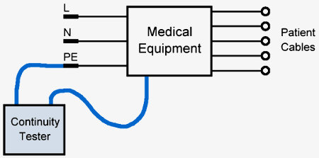 الجهاز مفصول عن الشبكة. Equipment is disconnected from mains.جهاز اختبار الاستمرارية موصول بالهيكل المعدني للجهاز وبـ PE في Continuity tester is connected to the metal housing of the equipment and to PE of the
قابس الشبكة. mains plug.
الجهاز مشغل. Equipment is switched on.المقاومة يجب أن تكون ≤ 0.2 ΩThe resistance should be ≤ 0.2 Ω
| للبلدان منخفضة الدخل: إذا لم يتوفر جهاز اختبار سلامة يمكن استخدام أوميتر بدقة جيدة. For low-income countries: When a safety tester is not present, an ohmmeter with good resolution can be used instead. |
2a. اختبار مقاومة العزل (الصنف I): يُقاس في هذا الاختبار العزل، ويلزم لذلك جهاز اختبار عزل (مثل Megger) يعطي الجهاز جهداً مستمراً عالياً للجهاز المختبر ثم تُقاس مقاومة العزل بينهما.
2a. Insulation resistance test (Class I)
With this test the insulation is measured. Therefore an insulation or safety tester (e.g. Megger) is needed. The tester delivers a high DC voltage to the equipment under test and then the resistance of the insulation in between is measured.جهد الاختبار القياسي للمعدات الكهربائية 500 V. أما الأجهزة الإلكترونية والطبية التي تحتوي غالباً عناصر تحديد جهد مثل MOV أو مرشحات EMI فتُختبر عند 250 V. Standard test voltage for electrical equipment is 500 V. Electronic and medical equipment which often contain voltage limiting devices such as MOV or EMI-filters should be tested at 250 V.
يُوصل جهاز الاختبار بين قابس الشبكة — مع توصيل L وN معاً — وPE. The tester is connected between the mains plug with L and N connected together and PE.
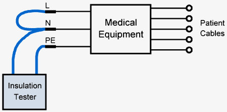 الجهاز مفصول عن الشبكة. Equipment is disconnected from mains.الجهاز مشغل. Equipment is switched on.جهاز اختبار العزل موصول بين L+N وPE. Insulation tester is connected between L+N and PE.
المقاومة يجب أن تكون ≥ 2 MΩ (للأجهزة الطبية) · ≥ 1 MΩ (للمحرك الكهربائي) · ≥ 0.3 MΩ (في الأجهزة ذات عنصر تسخين)The resistance should be ≥ 2 MΩ (medical equipment)
≥ 1 MΩ (on electric motor), ≥ 0.3 MΩ (on equipment with heating element)
| للبلدان منخفضة الدخل: يمكن إجراء اختبار تيار تسريب المريض (3a) بدل اختبار العزل. For low-income countries: Instead the insulation test a patient leakage current test can be done (3a). |
2b. اختبار مقاومة العزل (الصنف II): يختلف عن الصنف I لأن قابس الشبكة بلا اتصال PE. تُقاس مقاومة العزل بين كبلات المريض الموصولة معاً والأجزاء المعدنية المكشوفة غير المطليّة في الجهاز (كالمسامير والمقابس).
2b. Insulation resistance test (Class II)
The insulation resistance test for Class II equipment is different because the mains plug has no PE connection. The insulation resistance is measured between the patient cables which are all connected together and exposed and unpainted metal pieces (e.g. screws, sockets) of the equipment.جهد الاختبار القياسي للمعدات الكهربائية 500 V، والأجهزة الإلكترونية والطبية التي تحتوي غالباً عناصر تحديد جهد مثل MOV أو كبت EMI تُختبر عند 250 V. Standard test voltage for electrical equipment is 500 V. Electronic and medical equipment which often contain voltage limiting devices such as MOV or EMI suppression should be tested at 250 V.
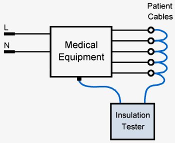 الجهاز مفصول عن الشبكة. Equipment is disconnected from mains.الجهاز مطفأ. Equipment is switched off.جهاز اختبار العزل موصول بين كل كبلات المريض والأجزاء المعدنية المكشوفة. Insulation tester is connected between all patient cables and exposed metal pieces.
المقاومة يجب أن تكون ≥ 2 MΩThe resistance should be ≥ 2 MΩ
| للبلدان منخفضة الدخل: يمكن إجراء اختبار تيار تسريب المريض (3c) بدل اختبار العزل. For low-income countries: Instead the insulation test a patient leakage current test can be done (3c). |
3. جهاز اختبار تيار التسريب: يمكن محاكاة تيار التسريب عبر جسم الإنسان وتحديده بإدخال معاوقة معلومة في اتصال الأرضي ثم قياس هبوط الجهد عليها. وجهاز القياس الموصى به يتكون من مقاومة 1 kΩ ومكثّف 0.15 µF على التوازي، ويجب أن تكون معاوقة الفولتميتر 1 MΩ على الأقل أي أن يكون رقمياً.
3. Leakage current test device
The leakage current through a human body can be simulated and determined by inserting a known impedance into the ground connection and then measuring the voltage drop across it. The recommended measuring device consists of a 1 kΩ resistor and a capacitor of 0.15 µF in parallel. The voltmeter has to have at least 1 MΩ impedance, so it has to be a digital one.اختبارات تيار التسريب بهذا الجهاز إجراءات قياسية للأجهزة الطبية وتوصي بها كل مصنّعي الأجهزة الطبية تقريباً. Leakage current tests with such a test device are standard test procedures for medical equipment and are recommended by almost all medical equipment manufacturers.
ونتيجة القياس المعروضة بالميلي فولت تساوي تياراً بالميكرو أمبير (1 mV ≙ 1 µA). The displayed measurement result in mV is equal to a current in µA (1 mV ≙ 1 µA).
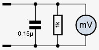
ويجب إجراء قياسات تيار التسريب الثلاثة المختلفة التالية، كل منها في حالتين: الحالة الطبيعية (NC) وحالة العطل المفرد (SFC) أي عند قطع اتصال الأرضي أو الحيادي. The following three different leakage current measurements should be made, each under two conditions: Normal condition (NC) and single fault condition (SFC), when the earth or neutral connection is interrupted.
تيار تسريب الأرضي Earth leakage currentتيار اللمس (تسريب الغلاف) Touch current (enclosure leakage current)تيار تسريب المريض Patient leakage current3a. اختبار تيار تسريب الأرضي (الصنف I): يحاكي هذا الاختبار ويقيس تيار تسريب عبر سلك الأرضي إلى الأرض، ويُجرى في وضع التشغيل الطبيعي وفي حالة العطل المفرد (حيادي مفتوح).
3a. Earth leakage current test (Class I)
This test simulates and measures a leakage current through the ground wire to earth. The test is done in normal operation mode and in single fault condition (open neutral).يمكن استخدام قياس تيار التسريب بديلاً عن اختبار مقاومة العزل (2a)، بل هو أفضل في الواقع لأن الجهد العالي في اختبار العزل قد يتلف الجهاز المختبر عند وجود MOV ومكثفات Y في مرشحات EMI. The measurement of the leakage current can be used as a substitute for the insulation resistance test (2a). In fact it is even better do this test instead because the high voltage of the insulation test may cause damages to the equipment on test when MOVs and Y-capacitors of EMI-filters are present.
يجب أن يكون الجهاز المختبر قيد التشغيل، وأن يُجرى القياس بقطبية شبكة طبيعية ثم معكوسة. The equipment under test has to be switched on. The measurement should be done with normal mains polarity and in reverse.
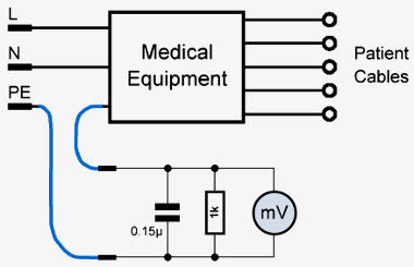
الحالة الطبيعيةNormal condition
الجهاز مشغل. Equipment is switched on.قطبية طبيعية Normal polarity قطبية معكوسة Reverse polarityتيار التسريب يجب أن يكون ≤ 0.5 mA (للأنواع B وBF وCF)Leakage current should be ≤ 0.5 mA (B, BF, CF)
حالة العطل المفرد — حيادي مفتوح NSingle fault condition - Open neutral, N
الجهاز مشغل. Equipment is switched on.قطبية طبيعية. Normal polarity.قطبية معكوسة. Reverse polarity.تيار التسريب يجب أن يكون ≤ 1 mA (للأنواع B وBF وCF)Leakage current should be ≤ 1 mA (B, BF, CF)
3b. تيار اللمس / تسريب الغلاف (الصنف I وII): يحاكي هذا الاختبار ويقيس تيار تسريب عبر السطح الموصّل المكشوف إلى الأرض، ويُجرى في وضع التشغيل الطبيعي وفي حالة العطل المفرد (حيادي مفتوح، PE مفتوح).
3b. Touch current / Enclosure leakage current (Class I and Class II)
This test simulates and measures a leakage current through the exposed conductive surface to earth. The test is done in normal operation mode and in single fault condition (open neutral, open PE).يجب أن يكون الجهاز المختبر قيد التشغيل، وأن يُجرى القياس بقطبية شبكة طبيعية ثم معكوسة. The equipment under test has to be switched on. The measurement should be done with normal mains polarity and in reverse.
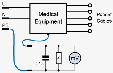
الحالة الطبيعيةNormal condition
الجهاز مشغل. Equipment is switched on.قطبية طبيعية. Normal polarity.قطبية معكوسة. Reverse polarity.تيار التسريب يجب أن يكون ≤ 0.1 mA (للأنواع B وBF وCF)Leakage current should be ≤ 0.1 mA (B, BF, CF)
حالة العطل المفرد — الأرضي الحام PE مفتوح (الصنف I فقط)Single fault condition - Open protective earth, PE (Class I only)
الجهاز مشغل. Equipment is switched on.قطبية طبيعية. Normal polarity.قطبية معكوسة. Reverse polarity.تيار التسريب يجب أن يكون ≤ 0.5 mA (للأنواع B وBF وCF)Leakage current should be ≤ 0.5 mA (B, BF, CF)
حالة العطل المفرد — حيادي مفتوح NSingle fault condition - Open neutral, N
الجهاز مشغل. Equipment is switched on.قطبية طبيعية. Normal polarity.قطبية معكوسة. Reverse polarity.تيار التسريب يجب أن يكون ≤ 0.5 mA (للأنواع B وBF وCF)Leakage current should be ≤ 0.5 mA (B, BF, CF)
3c. تيار تسريب المريض (الصنف I وII): يحاكي هذا الاختبار ويقيس تيار تسريب عبر توصيلات المريض إلى الأرض، ويُجرى في وضع التشغيل الطبيعي وفي حالة العطل المفرد (حيادي مفتوح، PE مفتوح).
3c. Patient leakage current (Class I and Class II)
This test simulates and measures a leakage current through the patient connections to earth. The test is done in normal operation mode and in single fault condition (open neutral, open PE).يجب أن يكون الجهاز المختبر قيد التشغيل، وأن يُجرى القياس بقطبية شبكة طبيعية ثم معكوسة. The equipment under test has to be switched on. The measurement should be done with normal mains polarity and reverse.
تُوصل كبلات المريض في أجهزة النوعين B وBF معاً ثم تُقاس مقابل الأرضي. وفي حالة جهاز من النوع CF تُقاس التيارات منفردة عبر كل توصيل للمريض إلى الأرضي. The patient leads of B and BF equipment are connected together and are then measured against earth. In case of an equipment of CF type the currents should be measured separately, through each patient connection to earth.
يجب أن يكون الجهاز المختبر قيد التشغيل، وأن يُجرى القياس بقطبية شبكة طبيعية ثم معكوسة. The equipment under test has to be switched on. The measurement should be done with normal mains polarity and in reverse.
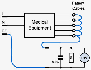
الحالة الطبيعيةNormal condition
الجهاز مشغل. Equipment is switched on.قطبية طبيعية. Normal polarity.قطبية معكوسة. Reverse polarity.تيار التسريب يجب أن يكون ≤ 0.1 mA (النوعان B وBF) و≤ 0.01 mA (النوع CF)Leakage current should be ≤ 0.1 mA (B, BF) ≤ 0.01 mA (CF)
حالة العطل المفرد — الأرضي الحام مفتوح (الصنف I فقط)Single fault condition - Open protective earth (Class I only)
الجهاز مشغل. Equipment is switched on.قطبية طبيعية. Normal polarity.قطبية معكوسة. Reverse polarity.تيار التسريب يجب أن يكون ≤ 0.5 mA (النوعان B وBF) و≤ 0.05 mA (النوع CF)Leakage current should be ≤ 0.5 mA (B, BF) ≤ 0.05 mA (CF)
حالة العطل المفرد — حيادي مفتوحSingle fault condition - Open neutral
الجهاز مشغل. Equipment is switched on.قطبية طبيعية. Normal polarity.قطبية معكوسة. Reverse polarity.تيار التسريب يجب أن يكون ≤ 0.5 mA (النوعان B وBF) و≤ 0.05 mA (النوع CF)Leakage current should be ≤ 0.5 mA (B, BF) ≤ 0.05 mA (CF)
ماذا يمكن عمله أيضاً؟ ينبغي تشجيع العاملين في المستشفى على الإبلاغ عن أي مشكلة (سلامة) أو تلف أو أثر غير معتاد إلى القسم التقني، وكذلك عن القوابس ومقابس الحائط التالفة والأجهزة ذات قوابس شبكة من النوع الخطأ.
What else can be done?
The hospital personnel should be encouraged to report any (safety) problem, damage or unusual effect to the technical department. This also applies to damaged plugs and wall sockets as well as equipment with mains plugs of the wrong type.عرّف العاملين بنظام القوابس الصحيح وأهمية استخدام المحولات (adapters)، وقدّم المحولات أو — أفضل — غيّر قوابس الطاقة الخاطئة. Inform the personnel about the right plug system and the importance of using adapters. Offer adapters or better change wrong power plugs.
وهذا يعني أيضاً توفّر عدد كافٍ من مقابس الحائط والقوابس الاحتياطية في المخزون وجاهزة في أي وقت؛ فلا معنى لشرح أهمية السلامة الكهربائية إذا لم تكن الإصلاحات تنفذ فوراً. But this also means that a sufficient number of spare wall sockets and mains plugs have to be in stock and available at any time. It does not make sense to explain the importance of electrical safety when the repairs can not be carried out immediately.
معظم مقابس الحائط في مستشفيات البلدان النامية اليوم مشغولة بشواحن هواتف العاملين، وهذا سيئ خصوصاً إذا انفصلت بسببه أجهزة المستشفى؛ فحتى الأجهزة غير المستخدمة الآن قد تحتاج الشبكة لشحن بطارياتها الداخلية. ناقش مع إدارة المستشفى منع شواحن الهواتف في أقسام المستشفى، ووفّر في المقابل منافذ شحن (مقابس موزعة) مثلاً في غرف الممرضين. Most of the wall sockets in hospitals in developing countries today are occupied by mobile phone chargers of the hospital staff. This is particularly bad when therefore hospital equipment is disconnected. Even when some equipment are not in use at the moment they might need mains in order to charge internal batteries. Discuss with the hospital management a ban for mobile phone chargers in hospital departments. But on the other hand also provide charging possibilities (distribution sockets) in e.g. nurses' rooms.
احتفظ بكمية كافية من قوابس الطاقة ومقابس الحائط الاحتياطية. Take a sufficient amount of spare mains plugs and wall sockets in stock.شجع العاملين على الإبلاغ عن أي تلف في القوابس ومقابس الحائط وكبلات Encourage hospital personnel to report any damage of plugs, wall sockets and powerالطاقة. cords.
أجرِ اختبارات منتظمة لكل قواطع RCD في المستشفى (مثلاً مرة كل سنة). Perform regular tests of all RCDs in the hospital (e.g. once a year).أجرِ اختبارات منتظمة لكل الأجهزة الطبية (كجزء من إجراءات الصيانة Perform regular tests of all medical equipment (as part of preventive maintenanceالوقائية). procedure).
أجرِ اختبارات سلامة بعد كل إصلاح. Conduct safety tests after every repair.روابط ومصادر
Links and sources
Wikipedia: Appliance classesWikipedia: Electrical safety testing
Wikipedia: Electric shock
Wikipedia: Portable appliance testing