
وحدات التغذية (Power Supplies)Power Supplies
وحدة التغذية تحوّل جهد الشبكة المتردد 230 V (125 V) إلى جهد مستمر منخفض ومستقر. والوحدة البسيطة تتكون من محوّل ومقوّم ومكثّف ومثبت بسيط. A power supply converts 230V (125V) AC mains into a low and stable DC voltage. A simple power supply consists of a transformer, a rectifier, a capacitor and a simple stabilizer.
أما الأجهزة الطبية المعقدة فتحتاج وحدات تغذية أفضل بتثبيت أكثر تطوراً، وكثيراً ما تعطي هذه الوحدات جهوداً اثنين وثلاثة وأكثر. For complex medical equipment, better power supplies with a more sophisticated stabilization are needed. Often these power supplies deliver two, three and more different voltages.
كثير من أعطال الأجهزة الطبية (والإلكترونية) سببها عيوب في وحدة التغذية؛ ولذلك يمكن إصلاح أجهزة كثيرة بمجرد معرفة طريقة عمل وحدات التغذية. Many failures of medical (and electronic) equipment due to power supply defects. Therefore a lot of devices can be repaired just with the knowledge of the functioning of power supplies.
الأنواع: وحدات التغذية «مصادر جهد»، أي إن جهد الخرج يبقى مستقراً حتى لو تذبذب تيار الخرج.
Types
Power supplies are 'voltage sources'. That means, that the output voltage is stable even if the output current fluctuates.أما شاحن البطارية مثلاً فهو «مصدر تيار»: يعطي تياراً مستقراً ويتغير الجهد حسب حالة شحن البطارية. Battery charger for example are 'current sources'. They deliver a stable current and the voltage changes depending on the state of charge of the battery.
الجهد المستقر مهم جداً في الإلكترونيات؛ فجهاز قياس (طبي حيوي) سيخرج عن مداه بتثبيت رديء ويعطي نتائج تشخيصية خاطئة. A stable voltage is very important in electronics. A (biomedical) measurement equipment will run out of range with a poor stabilization and will deliver wrong diagnostic results.
اليوم حلت وحدات التغذية التبديلية (switched-mode) الأرخص محل وحدات التغذية بمحولات ثقيلة غالية؛ فمحولاتها أصغر لكن إلكترونياتها أكثر. ونتيجة لصغر المحولات تكون أرخص لكن إصلاحها أصعب. Nowadays power supplies with expensive and heavy transformers are replaced by cheaper switched-mode power supplies. Switched-mode power supplies have smaller transformers but therefore more electronics. As a result of the smaller transformers they are cheaper but also more difficult to repair.
أجزاء وحدة التغذية البسيطة: في مراحل مختلفة يُحوّل جهد الشبكة المتردد العالي إلى جهد مستمر منخفض ومستقر.
The parts of a simple power supply
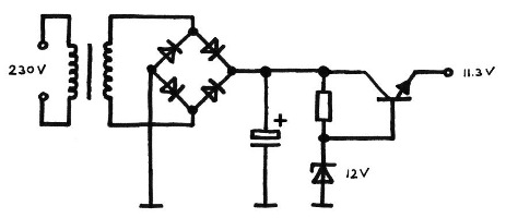
In different stages the high AC voltage is converted into a stable DC low-voltage.أولاً يُخفّض جهد الشبكة (المحوّل)، ثم يُحوّل إلى مستمر (المقوّم)، ثم يُرشَّح (المكثّف)، وأخيراً يُثبّت (ثنائي زينر وترانزستور أو دارة مثبت جهد). First the mains voltage has to be reduced (transformer), then converted to DC (rectifier), filtered (capacitor) and finally stabilized (zener diode and transistor or voltage stablizer IC).
|
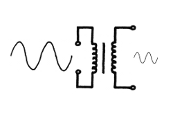
المحوّل يحول جهد الشبكة المتردد (230 V) إلى جهد متردد منخفض، وهذا يجب أن يحدث أولاً دائماً لأن المحولات لا تحوّل إلا المتردد.

The transformer transforms the mains AC voltage (230V) to low AC voltage. This has always to be done at first because transformers only can transform AC. |
|
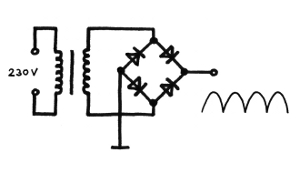
يصل الجهد المتردد الأصغر إلى المقوّم الذي يحوّل الجزء السالب من الموجة إلى إشارة موجبة.
The smaller AC voltage gets to a rectifier. The rectifier converts the negative part of the wave into a positive signal. |
|
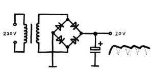
يُضاف مكثّف (صغير)، وقدرة المكثّف على تخزين الجهد تجعل الإشارة أكثر نعومة.
A (small) capacitor is added. The ability of voltage storage of the capacitor makes the signal smoother. |
|
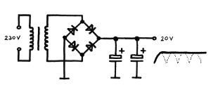
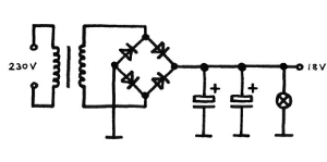
وإذا كانت السعة كبيرة بما يكفي يصبح إشارة الخرج مستوية تماماً، وقد أنشأنا جهداً مستمراً.
Is the capacity high enough the output signal is completely flat. We have created a DC voltage. |
|
تحت حمل أكبر ينهار الجهد المستمر؛ فبدل جهد دارة مفتوحة مثل 20 V نحصل على أقل من ذلك، وهذا غير مقبول لأن تذبذب الجهد يؤثر كثيراً في المراحل الموصولة. ومن المهم جداً الآن تثبيت جهد الخرج.
Under a bigger load the DC voltage breaks down. Instead of a open-circuit voltage of e.g. 20V we now have less. This is unacceptable because a voltage fluctuation has big influence to the connected stages. It is very important to stabilize the output voltage now. |
|
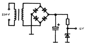
جهد الخرج الآن هو الجهد على ثنائي زينر، أي مستقر تماماً ضمن مدى مواصفات الثنائي. وتلزم دائماً مقاومة على التوالي يهبط عليها فرق الجهد (غير المستقر).
The output voltage now is the voltage across the zener diode. That means: absolutely stable within the range of the diode's specifications. A series resistor is always needed where the (unstable) voltage difference can drop. |
بهذه الدارة الصغيرة ننتج جهداً مستمراً نقياً ومستقراً جداً، لكن مع الأسف لا يمكن سحب إلا تيار صغير من دارة زينر هذه، وهو غير كافٍ لتشغيل التطبيقات الإلكترونية. With this little circuit we produce a very clean and stable DC voltage. But unfortunately only a small current can be taken from this zener diode circuit. For running electronic applications it is not enough.
للاستخدام العملي يجب تكبير هذا التيار، وهذه مهمة الترانزستور: فالجهد المستقر يتحكم الآن بدخل ترانزستور فقط، والترانزستور يضمن سحب تيار أعلى بكثير من الدارة. For a practical usage, this current has to be amplified. This is the job for a transistor. The stable voltage now controls just the input of a transistor and the transistor makes sure that a much higher current can be taken from the circuit.
وحدة تغذية بترانزستورPower Supply with Transistor
مبادئ الترانزستور
Transistor Principles
|
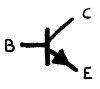
أطراف الترانزستور الثلاثة: القاعدة (Base) والباعث (Emitter) والمجمع (Collector).
The three pins of a transistor: Base, Emitter and Collector. |
تُستخدم الأطراف الثلاثة للدخل والخرج والتوصيل المشترك، وأي طرف هو ماذا يعتمد على التوصيل، وهناك ثلاثة تنويعات ممكنة. The three terminals are used for input, output and for the common connection. Which terminal is what depends on the wiring. Three variations are possible.
عموماً قاعدة الترانزستور هي طرف الدخل، وتيار الدخل يمر من القاعدة إلى الباعث. وعند مرور تيار يكون هبوط الجهد على BE كهبوط جهد الثنائي: 0.7 V دائماً. وهذا يعني أيضاً أنه تلزم دائماً مقاومة قاعدة تحدّ تيار القاعدة وتهبط الجهد الزائد. In general the Base of a transistor is the input lead. The input current flows from Base to Emitter. When a current flows the voltage drop across BE is like the voltage drop of a diode, always 0.7V. That also means that always a base resistor is needed which limits the base current and let drop the excessive voltage.
وتيار القاعدة هذا يتحكم بمسار CE في الترانزستور أي بتيار مجمع أعلى بكثير؛ فالترانزستور يعمل مكبراً: تيار قاعدة صغير يُسبب تيار مجمع كبيراً. فمثلاً تيار قاعدة 10 mA يمكن أن يتحكم بتيار حمل 1 A. This Base current now controls the CE path of the transistor which means a much higher Collector current. The transistor acts as an amplifier: A small Base current causes a big Collector current. For example a Base current of 10mA can control a load current of 1A.
من حيث المبدأ يتحكم تيار القاعدة بمسار CE؛ فمسار CE يفتح أو يغلق حسب تيار القاعدة. وكلما ارتفع تيار القاعدة صغر مسار CE (هبوط جهد CE) وارتفع تيار المجمع. In principle the Base current controls the CE path. The CE path opens or closes depending on the Base current. The higher the base current, the smaller the CE path (CE voltage drop) and the higher the Collector current will be.
بأقصى تيار قاعدة يكون الترانزستور مفتوحاً تماماً، والتيار أقصى وجهد CE أدنى. ويعمل الترانزستور حينها كمفتاح أو مرحّل. With the maximum base current the transistor is fully controlled, the current is maximum and the CE voltage is minimum. The transistor acts like a switch or relay.
|
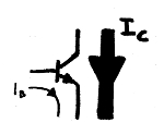
تيار قاعدة صغير يتحكم بتيار مجمع أكبر بكثير؛ وكلما ارتفع تيار القاعدة ارتفع تيار المجمع، وكلما ارتفع تيار المجمع صغر هبوط جهد CE.
A small Base current controls a much bigger Collector current. The higher the Base current, the higher the Collector current. The higher the Collector current, the smaller the CE voltage drop. |
وظيفة الترانزستور في وحدة التغذية: يُستخدم الترانزستور مكبرَ تيار، ونمط عمله الصحيح لذلك يسمى نمط المجمع المشترك (common-collector): القاعدة دخل تحكم، والمجمع دخل تغذية، والباعث خرج متحكم به.
Function of a power supply with a transistor
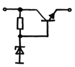
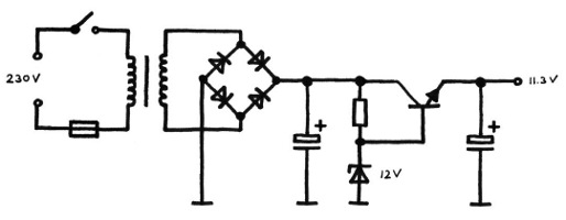
For a power supply the transistor is used as a current amplifier. The right transistor mode for this operation is called common-collector mode. This means the Base is used as control input, the Collector as power supply input and Emitter as the controlled output.يُستخدم الجهد المستقر لثنائي زينر للتحكم بالترانزستور، فيُوصل جهد الزينر بالقاعدة. وهذا ممكن لأن تيار القاعدة المطلوب صغير بما لا يؤثر في جهد الزينر. The stabilized voltage of the zener diode is used to control the transistor. The zener-voltage is connected to Base. This is possible because the needed Base current is low enough not to effect the zener voltage.
لا حاجة لمقاومة قاعدة إضافية لأن مقاومة زينر على التوالي تعمل أيضًا مقاومة على التوالي للترانزستور. An additional base resistor is not needed because the series resistor of the zener diode also acts as a series resistor for the transistor.
|
المجمع: جهد دخل غير مستقر · القاعدة: جهد تحكم مستقر · الباعث: جهد خرج (مستقر) متحكم به
Collector: Unstable input voltage Base: Stable control voltage Emitter: Controlled (stable) output voltage |
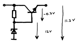
12 V − 0.7 V = 11.3 V 12V - 0.7V = 11.3V.
or
V(out) = V(Z-diode) − V(BE) Vout = VZ-diode - VBE
|
جهد الخرج مستقر لأن جهد الزينر وجهد BE مستقران، والجهدان على التوالي.
The output voltage is stable because the zener voltage and the BE voltage are stable. Both voltages are in series. |
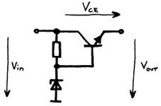
V(out) = V(in) − V(CE) Vout = Vin - VCE
|
عند تغير جهد الدخل يتغير جهد CE فقط لأن جهد القاعدة ثابت؛ وجهد الباعث (الخرج) ثابت أيضاً لأنه يعتمد على جهد القاعدة الثابت ناقص جهد BE الثابت 0.7 V.
When the input voltage changes only the CE voltage of the transistor changes because the Base voltage is fixed. The Emitter voltage (output voltage) is also fixed because it depend on the fixed Base voltage minus the fixed 0.7V Base-Emitter voltage. |
|
لم يبق إلا مفتاح شبكة ومصهر، وبذلك تكتمل وحدة التغذية. The only thing which is missing now, is a mains switch and a fuse. Then the power supply is complete.
|
قدرة أكبر: في الدارة السابقة أصبح العنصر المحدد هو الترانزستور؛ فمعاملاته تحدد جهد الخرج (أو بالأدق أقصى جهد EC) وأقصى تيار يمكن سحبه. والمهم دائماً هو الحالة بين المجمع والباعث، فهنا يمر تيار الحمل العالي وتتولد مع هبوط جهد CE حرارة الترانزستور.
More power
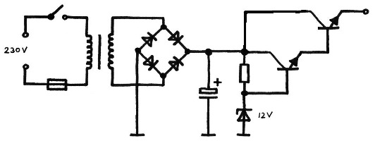
In the above shown circuit the limiting device now is the transistor. The parameters of the transistor defines the output voltage (or more precise the maximum EC voltage) and the maximum current which can be taken. Important is always the situation between Collector and Emitter. Here the high load current flows and together with the CE voltage drop the heat loss of the transistor is created.إذا كان على وحدة التغذية إعطاء تيار خرج أعلى أو كان الفرق بين جهد الدخل والخرج (V CE) كبيراً جداً فيلزم ترانزستور أكبر. ومع الأسف يحتاج الترانزستور الأكبر تيار قاعدة أكبر أيضاً يُجهد ثنائي الزينر ومن ثم التثبيت. وما نحتاجه هنا: ترانزستور إضافي يتحكم بالترانزستور الرئيسي — ترانزستران على التوالي، أحدهما يتحكم بالآخر. If the power supply has to deliver a higher output current or the difference between input and output voltage is too big (VCE) a bigger transistor is needed. Unfortunately a bigger transistor also needs a bigger base current which again stresses the zener diode and thus the stabilization. What we need in this case: An additional transistor. A transistor which controls the main transistor. Two transistors in series. One controls the other.
|
الترانزستور العلوي دائماً أكبر بكثير من الآخر لأن الحمل الرئيسي يمر فيه، أما السفلي فعليه إعطاء تيار القاعدة الصغير للكبير فقط. ووحدة تغذية كهذه تعطي عدة أمبيرات، لكن لاحظ أن هذا التيار العالي مع هبوط جهد CE ينشئ ضياع قدرة كبيراً أي حرارة، ولذلك يُثبَّت ترانزستور الحمل دائماً على مشتت حراري. The upper transistor is always much bigger than the other one, because the main load flows through this transistor, while the lower transistor only has to deliver the small base current for the big one. Such a power supply can deliver some Amps. But note, together with the CE voltage drop this high current creates a big power loss, which means heat. The load transistor always has to be mounted on a heat sink.
ونظرة أخرى إلى الجهود: Again a look at the voltages:
- جهد الزينر ثابت 12 V - Zener voltage is fixed at 12V
- هبوط BE في الترانزستور (الأصغر) ثابت أيضاً 0.7 V - Voltage drop BE of the first (smaller) transistor is also fixed at 0.7V
- الجهد عند E: (12 V − 0.7 V) = 11.3 V - Voltage at E: (12V - 0.7V)= 11.3V
- هبوط BE في الترانزستور الثاني (الأكبر) ثابت أيضاً 0.7 V - Voltage drop BE of the second (bigger) transistor is also fixed at 0.7V
- الجهد عند E وهو جهد الخرج: (11.3 V − 0.7 V) = 10.6 V - Voltage at E which is the output voltage: (11.3V - 0.7V) = 10.6V
- جهد الخرج مستقر لكنه 10.6 V فقط - The output voltage is stable but only 10.6V
- أو بالعكس: إذا أردنا خرجاً 12 V فيجب أن يكون ثنائي الزينر لـ - Or the other way round: If we need a 12V output voltage the zener diode has to be one for
13.4 V (12 V + 0.7 V + 0.7 V) 13.4V (12V + 0.7V + 0.7V)
ضياع القدرة: نظرة الآن على ضياع القدرة.
Power loss
Now a look at the power loss:التيار عبر الترانزستور مع هبوط الجهد بين C وE يعطي ضياع القدرة. وفي حالة ترانزستور الحمل العلوي قد يبلغ الضياع عدة واطات أي حرارة، فيسخن الترانزستور. ولهذا يُثبَّت ترانزستور الحمل دائماً على مشتت حراري أو مباشرة على هيكل الجهاز المعدني. والقاعدة التقريبية: كل عنصر شبه موصل بضياع قدرة أكبر من 1 W يحتاج مشتتاً حرارياً. The current through the transistor together with the voltage drop between C and E makes the power loss. In case of the upper load transistor there can be several watts of power loss, which means heat. The transistor gets hot. That is why the load transistor of a power supply is always mounted on a heat sink or directly to the metal housing of the equipment. The rule of thumb is: Every semiconductor with a power loss bigger than 1W needs a heat sink.
والحرارة أو ضياع القدرة هي حاصل ضرب هبوط جهد V CE في تيار الحمل عبر الترانزستور I CE. The power loss or heat is the product of the VCE voltage drop and the load current through the transistor ICE
P = I(load) × V(CE) P = Iload × VCE
الجهد السالب: والآن شيء مربك.
Negative Voltage
Now something confusing.يمكن لوحدات التغذية أيضاً توليد جهود سالبة، والتقنية نفسها المستخدمة للجهود الموجبة؛ فالمسألة مسألة تأريض أو موضع نقطة المرجع لقياسنا. Power supplies can also generate negative voltages. The technology is the same as for positive voltages. It is just a matter of grounding or where the reference point for our measurement is.
الجهد السالب يعني أن جهد الخرج أكثر سلبية بالنسبة للأرضي. Negative voltage means, that the output voltage is more negative against the ground.
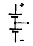
إذا وُصل الطرف الموجب لبطارية بالأرضي كان الطرف السالب أكثر سلبية من الأرضي، وجهد الخرج سالباً. Is the positive terminal of a battery connected to the ground, then the negative terminal is more negative than the ground. The output voltage is negative.
|
تخيل بطاريتين 9 V على التوالي: أولاً نوصل سالب البطارية السفلى (وكبل القياس) بالأرضي، فسنقيس في الوسط 9 V وفي الأعلى 18 V. الآن نضع نقطة الوسط في الأرضي (وكذلك كبل القياس): سنقيس في الأعلى 9 V وعند سالب البطارية السفلى −9 V. فنحصل على جهدين: موجب وسالب.
Imagine two 9V-batteries in series. First we connect the minus connection of the lower battery (and our measuring cable) to the ground. In the center we would measure 9V at the top 18V. Now we put the center point to the ground (and also our measuring cable). On top we would measure 9V and at the minus connector of the lower battery -9V. We get two voltages, a positive and a negative one. |
|
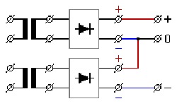
وبالطريقة نفسها تعمل وحدة تغذية لجهد موجب وجهد سالب: طرف + أكثر إيجابية وطرف − أكثر سلبية بالنسبة للأرضي.
In the same way a power supply for a positive and a negative voltage works. The + connection is more positive and the - connection more negative compare to the ground. |
وحدات تغذية بدارة مثبت IC: إلى جانب تثبيت الجهد يُطلب غالباً حماية من القصر وحماية من فرط الحرارة لوحدات التغذية، ومع ذلك يجب أن تكون الدارة أبسط وأصغر وأرخص ما يمكن.
Power Supplies with Stabilizer-IC
Beside voltage stabilization, often a short circuit protection and an overhead protection for power supplies are demanded. Nevertheless the circuit should be as simple, small and cheap as possible.والحل دارة متكاملة خاصة (IC) تحتوي كل هذه الوظائف؛ وأشهر مثبت هو سلسلة 78xx، وهذه الدارة تحتوي التثبيت كله ودارات السلامة كلها. The solution is a special IC (Integrated Circuit), which contains all these functions. The most common stabilizer is the 78xx series. This IC contains the whole stabilization and all the safety circuits.
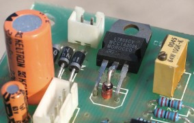
المثبت الموجب 78xx: للدارة ثلاثة أطراف وهي في علبة ترانزستور، وجهد خرجها ثابت، وتتوفر أنواع مختلفة لجهود مختلفة.
Positive stabilizer 78xx
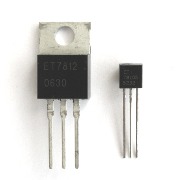
The IC has three pins and is build into a transistor housing. The output voltage is fixed. Different types for different voltages are available.
|
يبدو كالترانزستور لكنه دارة متكاملة معقدة؛ فالنوع 78xx (يسار) مثبت حتى 1 A، والأصغر 78Lxx (يمين) حتى 100 mA.
It looks like a transistors but it is complex integrated circuit. The 78xx type (left) is a stabilizer for up to 1A and the smaller 78Lxx (right) for up to 100mA. |
|
توجد هذه الجهود في سلسلة 78xx.
78xx for these voltages exist. |
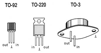
يعتمد توصيل الأطراف على نوع العلبة. ومن المفيد معرفة أن الجزء المعدني في 78xx هو الأرضي، ولذلك يمكن تثبيت الدارة على مشتت حراري دون أي عزل. The pin connection depends on the case type. Good to know that the metal part of 78xx is ground. The IC can mounted directly to a heat sink without any isolation.
|
توصيل أطراف النوع الموجب 78xx. والنوع الأكثر شيوعاً هو نوع 1 A في علبة TO-220، والأطراف هي: يسار — دخل، وسط — أرضي، يمين — خرج.
The pin connection for the positive 78xx type. The most common type is the 1A type in the TO-220 case. The connection pins are: left - in center - ground right - out |
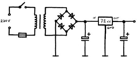
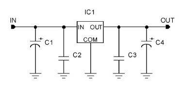
التطبيق بسيط: لا يلزم إلا مكثّف دخل ومكثّف خرج صغير لوحدة تغذية مثبتة تماماً. والوحدة محمية من القصر وتعطي حتى 1 A. The application is simple. Only a input capacitor and a small output capacitor is needed for a fully stabilized power supply. The power supply is short circuit protected and delivers up to 1A.
|
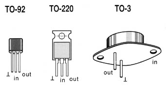
المثبت السالب 79xx: إلى جانب 78xx الموجب توجد مثبتات للجهود السالبة هي سلسلة 79xx، وهي متشابهة المظهر لكن أطراف التوصيل مختلفة.
Negative stabilizer 79xx
Beside the positive 78xx also a stabilizers for negative voltages exist. It is the 79xx series. The stabilizer look similar but the connecting pins are different.
|
توصيل أطراف النوع السالب 79xx: يسار — أرضي، وسط — دخل، يمين — خرج (والنوع الأكثر شيوعاً 1 A في علبة TO-220).
Here the pin connection for the negative 79xx type. The most common type is the 1A type in the TO-220 case. The connection pins are: left - ground center - in right - out |
مهم:Important:هذه المرة العلبة المعدنية ليست الأرضي. This time the metal case is NOT ground.
المثبت السالب متوفر أيضاً لجهود خرج مختلفة؛ فـ 7912 مثبت −12 V. Also the negative stabilizer is available for different output voltages. A 7912 is a -12V stabilizer.
|
توجد هذه الجهود السالبة في سلسلة 79xx.
79xx for these negative voltages exist. |
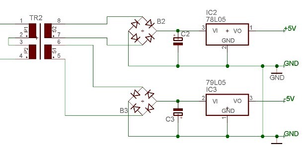
دارة التغذية التالية من جهاز تركيز أكسجين تجمع وحدتين، واحدة لجهد موجب وأخرى لجهد سالب. The following power supply circuit from an oxygen concentrator combines two power supplies, one for a positive and one for the negative voltage.
|
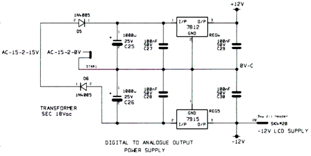
وأدناه وحدة تغذية مشابهة في مطياف. Below a similar power supply of a spectrometer.
|
(بالمناسبة هناك خطأ في الدارة؛ انظر إلى الجهود خصوصاً في الجزء السالب...) (By the way, there is a fault in the circuit. Look at the voltages specially in the negative part...)
استكشاف الأعطال والمشكلات الشائعة: أسباب الأعطال في الدارات الإلكترونية عموماً هي دائماً التيارات العالية والجهود العالية وضياعات القدرة وما ينتج عنها من حرارة كبيرة، وكل هذا ينطبق على وحدات التغذية. ولهذا يجب أن يبدأ استكشاف الأعطال في الأجهزة الإلكترونية دائماً بفحص جهد (جهود) وحدة التغذية.
Troubleshooting and common problems
Reasons for defects in electronic circuits in general are always high currents, high voltages and power losses with the development of big heat. All this applies to power supplies. That is why troubleshooting in electronic equipment should always start with checking the voltage(s) of the power supply.نظرياً لا ينبغي أن يتلف منظم الجهد أبداً لأنه محمي من القصر ومن فرط الحرارة، لكنه في العمل يتلف أحياناً (لماذا؟ لا أعرف). In theory voltage regulators should never fail because they are protected against short circuit and over heating. But in practice they sometimes gets broken. (Why? - I don't know.)
يجب إجراء فحص الوظيفة تحت الجهد. ومع أن المثبتات تشبه الترانزستورات فهي دارات متكاملة، ولا يمكن فحص المثبت بأوميتر! A function check has to be done under power. Even if stabilizers look like transistors, they are ICs. You can not check a stabilizer with an ohm-meter!
فحص الجهد سهل جداً: A voltage check is very easy:
 صل مقياسك المتعدد بالأرضي (الهيكل المعدني، سالب أكبر مكثّف...) Connect your multimeter to the ground (metal housing, minus of biggest capacitor...)الطرف الأيسر جهد الدخل (حتى 30 V)، والوسط أرضي (0 V)، واليمين هو Left pin is input voltage (up to 30 V), center is ground (0 V) and the right pin is the
(في نوع 78xx الشائع) common 78xx type)
توصيل أطراف المنظمات السالبة (79xx) مختلف (أرضي — دخل — خرج). The pin connection of negative regulators (79xx) is different (ground - input - output).فكر في حماية القصر عند غياب جهد الخرج؛ فغياب الخرج قد يعني أن المثبت تالف ولا يعطي جهداً، لكنه قد يعني أيضاً وجود قصر بعد وحدة التغذية وأن الحماية المدمجة تسحب الجهد إلى الأسفل. ولذلك افصل الحمل دائماً عن المثبت عند غياب الجهد: انزع الكبلات إلى المراحل الموصولة أو اقطع طرف الخرج في الدارة بمقرض صغير، وحينها تفحص جهد الخرج عند الدارة مباشرة، ثم تلحمه لاحقاً. Think about the short circuit protection when there is no output voltage. No output voltage can mean, that the stabilizer is defective and delivers no voltage. But it also can mean, that there is a short circuit after the power supply and the integrated protection pulls the voltage down. Therefore, always disconnect the load from the stabilizer if there is no voltage. Just take off the cables to the connected stages or cut the output leg of the IC with a small cutter. Now you can check the output voltage directly at the IC. Later you can solder it again.
|
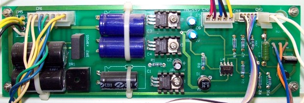
هذه وحدة تغذية مطياف؛ يُرى بوضوح مكثفات الشحن الكبيرة على اليسار وفي الوسط، وبينها مقوّمان، وثلاثة مثبتات على مشتتات حرارية صغيرة. This is the power supply of a spectrometer. Clearly to see the big charging capacitors at the left and in the center, two rectifiers in between and three stabilizer mounted on small heat sinks.
أول خطوة لفحص اللوح: وصل سالب فولتميتر بالأرضي (سالب المكثفات، أو أوسع مسار نحاسي، أو الطرف الأوسط في مثبت 78xx). وجهد الدخل غير المستقر على الطرف 1، وجهد الخرج المستقر على الطرف 3. First step for checking the board is: Connecting minus of the voltmeter to the ground (minus of the capacitors, the largest conductor track or the center pin of the stabilizer 78xx). The unstable input voltage is at pin 1, the stable output voltage is at pin 3.
تذكر أن المثبتات السالبة 79xx لها توصيل أطراف مختلف. Remember, negative 79xx stabilizer have different pin connection.
|
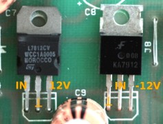
وهذه مرة أخرى أطراف 78xx و79xx
Here again the pin connections of a 78xx and a 79xx |
إذا كان المثبت تالفاً والنوع الصحيح غير متوفر فقد يمكن أخذ آخر؛ والحيلة أن تأخذ مثبتاً لجهد أقل وترفع الأرضي بثنائي زينر، فجهد الزينر وجهد المثبت يعطيان جهد الخرج. If a stabilizer is defective and the right one is not available, maybe another one can be taken. The trick is to take a stabilizer for a lower voltage and putting up the ground by a zener diode. Zener voltage and stabilizer voltage make the output voltage.
|
ويمكن الحصول على خرج 9 V (8.9 V) بمثبت 5 V عادي وثنائي زينر 3.9 V.
A 9V-output voltage (8.9V) can be created by a common 5V-stabilizer and a 3.9V-Zener-diode. |
اصنع وحدة تغذية بدارة مثبت IC: كثيراً ما نحتاج وحدة تغذية: جهاز يعمل على البطارية يجب أن يعمل على جهد الشبكة، أو وحدة التغذية الخارجية لجهاز مثل المجهر تالفة ولا تُصلح. في هذه الحالة يمكنك بناء وحدة تغذية بنفسك، لكن البناء يحتاج بعض الخبرة وبعض الحسابات.
Do-it-yourself power supply with stabilizer IC
A power supply is often needed. A battery powered equipment shall run on mains voltage or the defective external power supply of e.g. a microscope is not repairable. In this case a power supply can be build by yourself. But for the construction some experiences are needed and some calculations have to be done.وهذه بعض الإشارات العامة لحساب قيم القطع المطلوبة: Here some universal hints to calculate the values of the needed parts:
المحوّل:Transformerجهد الخرج يجب أن يكون أعلى بـ 3-5 V من جهد التيار المستمر المطلوب (غير المستقر)، وتيار الخرج أعلى بـ 10-20% من تيار التيار المستمر المطلوب.: Output voltage should be 3-5V higher than the needed (unstable) DC voltage. The output current should be 10-20% higher than the needed DC current.
المقوّم:Rectifierجهد الإثبات يجب أن يكون 1.4 × جهد خرج المحوّل على الأقل.: The proof voltage must be at least 1.4 x transformer output voltage.
المكثّف 1:Capacitor 1مكثّف الشحن بأكبر سعة ممكنة؛ 470 µF لكل 100 mA مثالي، وجهد الإثبات 1.4 × جهد المحوّل على الأقل.: Charging Capacitor as big as possible. 470µF per 100mA is perfect. Proof voltage at least 1.4 x UTransformer
المثبتStabilizerضياع قدرة أكبر من 1 W يلزم معه مشتت حراري. P = (U out − U in) × I: Power loss bigger than 1W always with heat sink. P = (Uout - Uin) x I
المكثّف 2:Capacitor 2مكثّف الخرج: 220 µF لتطبيقات الصوت و10 µF لغيرها، وجهد الإثبات 1.4 × جهد المثبت على الأقل.: Output capacitor. For Audio applications 220µF, for all others 10µF. Proof voltage at least 1.4 x UStabilizer
|
كثيراً ما تجد مكثفين صغيرين غير مستقطبين C2 وC3 في مسار دخل وخرج المثبت، وظيفتهما كبت التذبذب غير المرغوب في الدارة، ويجب تثبيتهما قرب المثبت، وقيمهما غير حرجة و0.1 µF شائعة.
Often you find two small bipolar capacitors C2,C3 in the input and output path of the stabilizer. Their task is to suppress unwanted oscillating of the IC. They should be mounted close to the stabilizer. The values are not critical. 0.1µF are common. |
الأسعار: دارات المثبت رخيصة وقطع غيار إلكترونية قياسية، وبعض الأنواع — خاصة 7805 و7812 — ينبغي أن تتوفر في كل ورشة.
Prices
Stabilizer ICs are cheap and standard electronics spare parts. Some types specially the 7805 and the 7812 should be present in every workshop.| 78xx، 79xx (TO-220)78xx, 79xx (TO-220) | 0.30 € |
| 78Lxx، 79Lxx (TO-92)78Lxx, 79Lxx (TO-92) | 0.20 € |
| 78xxK، 79xxK (TO-3)78xxK, 79xxK (TO-3) | 1.50 € |
روابط ومصادر
Links and sources
Wikipedia: Power supplyWikipedia: Switched-mode power supply
Wikipedia: Voltage stabilizer