
قانون أوم وتطبيقات المقاوماتOhm's Law and Resistor Application
جهد التيار المستمر: نتعامل في الإلكترونيات عادةً مع جهود مستمرة منخفضة (DC)، والشائع جهود تغذية بين 5 V و24 VDC، وكثيراً ما تُصمّم الدارات على 12 V.
DC voltage
In electronics we usually deal with low voltage DC (Direct Current). Supply voltages between 5 V and 24 VDC are common. Very often electronic circuits are designed for 12 V.كبلات التغذية في التركيبات الكهربائية تسمى الطور (P) والحيادي (N)، أما في التيار المستمر فكبلتا التغذية موجب (+) أحمر وسالب (−) أسود. Supply cable in electrical installation are called phase (P) and neutral (N). In DC the two supply cables are plus (+) (red) and minus (-) (black).
عموماً السالب هو التوصيل المشترك، ويُوصل غالباً بالأرضي وبالهيكل المعدني للجهاز. In general minus is the common connection. Often it is grounded and connected to the metal housing of the equipment.
لتشغيل دارة كهذه على جهد الشبكة يلزم مصدر تغذية يحول جهد الشبكة المتردد العالي (مثل 230 V) إلى جهد مستمر منخفض، مثل: 230 VAC ← 12 VDC. In order to run such a circuit on mains voltage a power supply is needed. The power supply converts the high voltage (e.g. 230 V) mains AC (Alternating Current) into low voltage DC, for example: 230 VAC → 12 VDC.
يمكن تحويل الجهود المترددة (تصغيراً أو تكبيراً) بمحوّل وبضياعات قليلة، أما تحويل جهد مستمر بلا ضياع فليس بهذه السهولة؛ ويمكن أيضاً تحويل المتردد إلى مستمر بسهولة بمقوّم، أما العكس — تحويل المستمر إلى متردد — فليس سهلاً كذلك. AC voltages can be transformed (making a voltage smaller or bigger) by means of a transformer without much losses. A powerless transformation of a DC voltage is not that easy. An AC voltage can also easily converted into a DC voltage by a rectifier. The other way round, converting a DC voltage into an AC voltage is also not that easy.
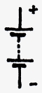
| الجهد V يُقاس بالفولت (V)، والدارات الإلكترونية تعمل عادةً بالتيار المستمر. The voltage V is measured in V (Volt). Electronic circuits usually run on DC. |
|
البطارية مصدر نمطي للتيار المستمر، وهي توصيل عدة خلايا (بطاريات) مفردة. A battery is a typical DC power source. A battery is a connection of several single (battery) cells. |
قياس الجهد: يمكن قياس الجهد بفولتميتر أو بمقياس متعدد يتضمن فولتميتر. والفولتميترات الرقمية أسهل قراءةً لكنها ليست بالضرورة أدق؛ فالدقيق هو الفولتميتر المعاير فقط، تناظرياً كان أو رقمياً، رخيصاً أو غالياً.
Measuring a voltage
The voltage can be measured with a voltmeter or a multimeter which includes a voltmeter. Digital voltmeters are easier to read but not necessarily more accurate. Only a calibrated voltmeter is precise, no matter if it is analogue or digital, cheap or expensive.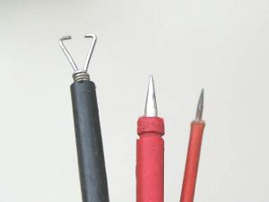 |
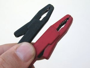
ملاقط وأطراف لقياس الجهود. Clamp and tips for measuring voltages. |
ولأن وجود الجهد شرط للدارة الكهربائية، فإن أول قياس في دارة معطلة هو دائماً فحص جهد التشغيل. Because an existing voltage is a condition for an electric circuit, the first measurement in a defective circuit is always the checking of the operating voltage.
الدارة الكهربائية: تتكون الدارة من مصدر جهد وحمل، وإذا كانت مغلقة أمكن مرور التيار.
Electric circuit
An electric circuit consists of a voltage source and a load. If the circuit is closed a current can flow.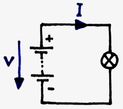 |
دارة بسيطة بمصدر جهد ومصباح. Simple circuit with voltage source and a light bulb. |
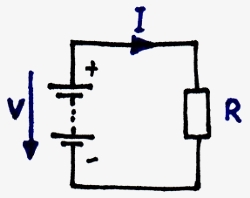 |
وهذه الدارة المكافئة بمقاومة. Here the equivalent circuit with a resistor. |
ويُقاس جهد وحدة التغذية على طرفي وحدة التغذية. The voltage of the power supply is measured across the power supply.
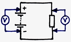 |
وفي هذه الحالة يكون الجهد على المقاومة مساوياً لجهد التغذية. In this case the voltage across the resistor and the voltage of the supply supply is the same. |
التيار: الشرط الأول للتيار وجود جهد، والثاني الدارة المغلقة.
Current
The first condition for a current is an existing voltage, second the closed circuit.التيار في الدارة المغلقة واحد في كل مكان ويمكن قياسه في أي موضع. The current in a closed circuit is everywhere the same and can be measured everywhere.
إذا كان الجهد مستمراً فالتيار مستمر أيضاً. Is the voltage DC also the current is DC.
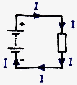
|
في الدارة البسيطة يكون التيار واحداً في كل مكان. In a simple circuit the current is everywhere the same. |
| يُقاس التيار I بالأمبير (A) أو mA. The current I is measured in A or mA (Ampere). |
قياس التيار: يمكن قياس التيار بأميتر وهو مدمج دائماً في المقياس المتعدد.
Measuring a current
The current can be measured with an ammeter which is always integrated in a multimeter.وخلافاً للفولتميترات تكون جودة الأسلاك والملامسات والملاقط مهمة، لأن تيار الدارة كلها يمر في الأميتر والأسلاك والموصلات؛ وكلما ارتفع التيار وجب أن تكون الموصلات والكبلات والملاقط أكبر. Compare to voltmeters the quality of the leads, the contacts and the clamps are import because the current of the whole circuit flows through the ammeter, the leads and connectors. The higher the current, the bigger the connectors, cable and clamps have to be.
|
ملاقط مناسبة لقياس التيارات.
Appropriate clamps for measuring currents. |
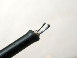 |
استُخدمت ملقطة قياس جهد صغيرة لقياس التيار، فالأمهلة التيار العالي. A small voltage measurement clamp was used for current measurement. The high current destroyed the clamp. |
| لا يجوز استخدام أطراف وملاقط قياس الجهد لقياس التيار. Tips and clamps for voltage measurement must not be used for current measurement. |
في الهندسة الكهربائية تشيع مقاييس الملقط؛ فالقياس يتم دون تلامس عبر المجال الكهربائي حول الموصل الذي يعتمد على التيار. وهي ليست دقيقة كثيراً ولا تُستخدم إلا للتيارات العالية. In electrical engineering clamp meters are common. The measurement happens contact-less through the electrical field around the conductor which depends on the current. Clamp meters are not very precise and can be only used for high currents.
في الإلكترونيات ليس قياس التيار عبر مقاومة شائعاً كثيراً، ولأن التيار يعتمد على الجهد والمقاومة فيمكن قياسه بشكل غير مباشر من الجهد على المقاومة (قانون أوم). In electronics the measurement of the current through a resistor is not very common. Because the current depends on the voltage and the resistor, the current can be measured indirectly by the voltage across a resistor (Ohm's law).
المقاومات: لكل جهاز كهربائي أو إلكتروني مقاومة كهربائية، وحتى الكبلات لها مقاومة تعتمد على طولها وقطرها ومادتها.
Resistors
Every electrical or electronic device has a electrical resistance. Even cable have resistances. Those cable resistances depends on the lengths, the diameter and the material of the cable.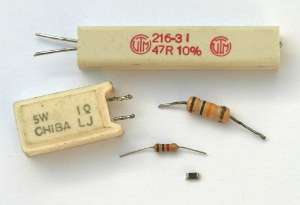 |
تُوجد المقاومات في كل الدارات الإلكترونية، وهي متوفرة بقيم وأحجام وأشكال مختلفة.
In electronic circuits resistors are found everywhere. They are available in different values, sizes and shapes. |
| تُقاس المقاومة R بالأوم (Ω) أو kΩ أو MΩ. The resistance R is measured in Ω, kΩ or MΩ (Ohm). |
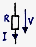
لاستكشاف أعطال الإلكترونيات نهتم بمقاومة المقاومة، والجهد عليها، والتيار عبرها. ويمكن تحديد التيار بقياس الجهد على المقاومة وحسابه مع المقاومة نفسها (I = V R / R). For troubleshooting electronics we are interested in the resistance of a resistor, the voltage across the resistor and the current through the resistor. The current can be determined by measuring the voltage across the resistor and the calculation with the resistance itself (I = VR / R).
|
المقاومة R تؤثر في الجهد على المقاومة (V R) والتيار عبرها (I R). The resistance R has influence on the voltage across the resistor (VR) and the current through the resistor (IR). |
قياس المقاومة: تُقاس المقاومة بأوميتر مدمج دائماً في المقياس المتعدد.
Measuring a resistor
The resistor can be measured with an ohmmeter which is always integrated in a multimeter.وللقياس يجب فصل المقاومة عن الدارة، وإلا أثرت بقية الدارة ومقاوماتها في نتيجة القياس. For the measurement the resistor has to be disconnected from the circuit. Otherwise the rest of the circuit with its resistances influences the measurement result.
وينطبق الأمر نفسه عند إمساك المقاومة باليدين: يمكن لمس المجس وطرف اتصال المقاومة من جهة واحدة، لا الجهتين، لأن مقاومة الجسم ستكون على التوازي مع المقاومة المختبرة. The same applies when holding the resistor in hands. On one side the probe and the resistor connection wire can be touched but not on both sides because the body resistance will be in parallel with the resistor on test.
المقاومة التالفة: المقاومات عادةً تحترق وتصبح عالية المقاومة (اتصال مفتوح) بسبب تيار مفرط. وهذا يعني: إذا احترقت مقاومة فلا بد من سبب للتيار الأعلى في مكان ما، ويكون غالباً عنصراً شبه موصل (ترانزستور، FET...) قُصر وأنتج التيار العالي غير الطبيعي.
Defective resistor
Typically resistors get burned. They get high-ohmic (open connection) because of excessive current. This means: When a resistor got burned, there must be a reason for the higher current somewhere. Often it is a semiconductor (transistor, FET...) which got a short and produced the abnormal high current.قانون أوم: مقاومة المقاومة R، والتيار عبرها I، والجهد على طرفيها V مترابطة ويُعبَّر عنها بقانون أوم:
Ohm's law
The resistance R of a resistor, the current I trough the resistor and the voltage V across the resistor are related together and are expressed in Ohms law:|
|
V = R × IV = R x I |
إذا عُرفت قيمتان من الثلاث يمكن حساب الثالثة. If two of the three values are known, the third can be calculated.
وصيغ القانون الثلاث هي: The three variations of this formula are:
| V = R × I أو I = V / R أو R = V / I V = R x I or I = V / R or R = V / I |
مهم:Important:
الوحدات المستخدمة في القيم هي V وA وΩ. The values for the units are V, A and Ω.
kΩkΩويمكن استخدامها إذا كان التيار مقدراً بـ can be used if the current is rated in mA.
قانون أوم أهم صيغة في الإلكترونيات، وكل من يعمل في هذا المجال يجب أن يعرفه عن ظهر قلب. ولتذكر الصيغة هناك طريقة بسيطة: Ohm's law is the most important formula in electronics. Everybody who works in the field of electronics has to know the law by heart. To remember the formula there is a simple method:
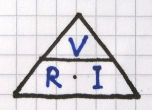 |
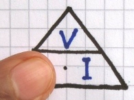
تخيل أو ارسم هرماً بالقيم الثلاث، والجهد V في الأعلى.
Imagine or draw a pyramid with the three values. The voltage V has to be up. |
| 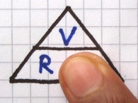 |
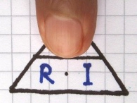 |
مثال 1: Example 1:مقاومة على تغذية 12 V تمرر 1 A. A resistor at a power supply of 12 V creates 1 A.
فما قيمة المقاومة؟ What is the value of the resistor?
R = V / I → R = 12 V / 1 A R = V / I R = 12 V / 1 A R = 12 ΩR = 12 Ω
مثال 2: Example 2:فما التيار الذي تمرره مقاومة 120 Ω على التغذية نفسها؟ What current creates a resistor of 120 Ω at the same power supply?
I = V / R → I = 12 V / 120 Ω I = V / R I = 12 V / 120 Ω I = 0.1 A أو 100 mAI = 0.1 A or 100mA
مثال 3: Example 3:عبر المقاومة 120 Ω نفسها يمر الآن 41.7 mA فقط. Through the same 120 Ω now flows only 41.7 mA.
فماذا حدث لوحدة التغذية؟ What has happened to the power supply?
V = R × I → V = 120 Ω × 0.05 A V = R x I V = 120 Ω x 0.05 A V = 6 VV = 6 V
جهد التغذية تغير إلى 6 V. The voltage of the power supply has changed to 6 V.
القصر: في الدارة التالية تُجسّر المقاومة، فتصبح مقاومتها 0 والتيار أقصى ما يمكن؛ فتتلف البطارية وقد تشتعل الأسلاك والبطارية. ولمنع هذا الوضع الخطير يوجد في كل وحدة تغذية وكل جهاز مصهر.
Short circuit
In the following circuit the resistor is bridged. The resistor now is 0 and the current is maximum. The battery will get damaged and wires and battery can burn. To prevent this dangerous situation every power supply and every equipment has a fuse.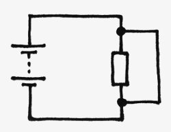
|
المقاومة 0، والتيار أقصى، والجهد 0. The resistance is 0. The current is maximum. The voltage is 0. |
انصهار المصهر له سبب؛ فلا تكتف بتغيير المصهر، بل ابحث أولاً عن سبب التيار العالي. A blown fuse has a reason. Do not only change the fuse. Find the reason for the high current first.
الدارة المفتوحة: في الدارة المفتوحة لا يمر تيار، ولا يُنشئ تيار هبوط جهد على المقاومات.
Open circuit
In an open circuit no current can flow and no current can create a voltage drop across the resistors.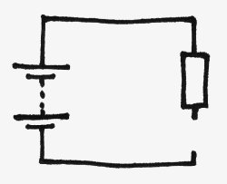
|
التيار 0، والجهد على المقاومة 0، والجهد قبل المقاومة وبعدها واحد. The current is 0. The voltage across the resistor is 0. The voltage in front of the resistor and behind is the same. |
توصيل المقاومات على التوالي: في دارة بمقاومتين أو أكثر على التوالي يوجد مسار واحد فقط للتيار: عبر المقاومتين معاً.
Series connection of resistors
In a circuit with two or more resistors in series there is only one path for the current to flow: Through both resistors. التيار عبر المقاومتين واحدThe current through both resistors is the same.لكن لأن المقاومتين قد تكونان مختلفتين فإن التيار نفسه يُنشئ هبوطي جهد مختلفين عليهما. But because the resistors might be different the same current creates different voltage drops across the resistors. هبوطا الجهد على المقاومتين مختلفانThe voltage drops across the resistors are different.
ويمكن حساب هبوطي الجهد بسهولة بقانون أوم. The voltage drops can be easily calculated by using Ohm's law.
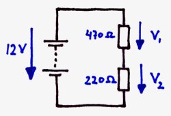 |
التيار عبر المقاومتين واحد، ويمكن حساب هبوطي الجهد إذا عُرفت قيمتا المقاومتين. The current through both resistors is the same. The voltage drops across the resistors can be calculated when the resistor values are known. |
في الدارة أعلاه نعرف الجهد الكلي والمقاومتين. For the circuit above we know the overall voltage and the two resistors.
أولاً نحسب التيار عبر المقاومتين: First we can calculate the current through both resistors:
I = V / R(total) → I = V / (470 Ω + 220 Ω) I = V / Rtotal I = V / (470 Ω + 220 Ω) I = 17.4 mAI = 17.4 mA
ثم نحسب هبوط الجهد على كل مقاومة: Then we calculate the voltage drop across each resistor:
V 1 = R 1 × I → V 1 = 470 Ω × 0.0174 A V1 = R1 x I V1 = 470 Ω x 0.0174 A V 1 = 8 VV1 = 8 V
V 2 = R 2 × I → V 2 = 220 Ω × 0.0174 A V2 = R2 x I V2 = 220 Ω x 0.0174 A V 2 = 3 VV2 = 3 V
(أو V 2 = V − V 1 = 12 V − 8 V) (or V2 = V – V1 V = 12 V – 8 V)
في العمل يُوصل مجس الفولتميتر السالب بالأرضي أو المشترك ويبقى هناك، ولا تُجرى القياسات إلا بالمجس الموجب. فنحن نقيس بالنسبة للأرضي، ولأن هوبوط الجهد جزء من جهد التغذية الكلي فيمكن حسابها بسهولة. In practice the minus probe of the voltmeter is connected to ground or common and remains there. Measurement are only made by using the plus probe of the multimeter. We are measuring against ground. Because the voltage drops are part of the overall power supply voltage can be easily calculated.
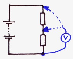 |
الجهد V 1 هو فرق جهد التغذية وV 2؛ وبعبارة أخرى: الجهد قبل المقاومة ناقص الجهد بعدها يعطي هبوط الجهد عليها. The voltage V1 is the difference of the power supply voltage and V2. In other words: The voltage in front of a resistor minus the voltage behind the resistor makes the voltage drop across the resistor. |
التوصيل على التوازي: في دارة التوازي تكون كل المقاومات على التوازي مع مصدر الجهد.
Parallel connection
In a parallel circuit all resistors are parallel to the voltage source. هبوطا الجهد على المقاومتين متساويانThe voltage drops across the resistors are the same.لكن لأن المقاومتين قد تكونان مختلفتين فليس التياران عبرها متساويين. But because the resistors might be different the currents through the resistors are not the same. التياران عبر المقاومتين مختلفانThe currents through the resistors are different.
ويمكن حساب هذين التيارين بسهولة بقانون أوم. These currents can be easily calculated by using Ohm's law.
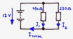 |
الجهد على المقاومتين واحد، ويمكن حساب التيارين إذا عُرفت القيمتان. The voltage across both resistors is the same. The currents through the resistors can be calculated when the resistor values are known. |
في الدارة السابقة نعرف الجهد الكلي والمقاومتين. For the previous circuit we know the overall voltage and the two resistors.
والتيار الكلي غير معروف. The total current is not known.
للحصول على التيار الكلي نحسب التيارين الجزئيين ونجمعهما. To get the total current we have to calculate the 2 partial currents and add them.
I 1 = V / R1 → I 1 = 12 V / 470 Ω → I 1 = 25.5 mA I1 = V / R1 I1 = 12 V / 470 Ω I1 = 25.5 mA
I 2 = V / R2 → I 2 = 12 V / 220 Ω → I 2 = 54.5 mA I2 = V / R2 I2 = 12 V / 220 Ω I2 = 54.5 mA
I(total) = I 1 + I 2 → I(total) = 25.5 mA + 54.5 mA Itotal = I1 + I2 Itotal = 25.5 mA + 54.5 mA I(total) = 80 mAItotal = 80 mA
التيار الكلي 80 mA.The total current is 80 mA.
ويمكن أيضاً حساب المقاومة الكلية ثم التيار الكلي. We can also calculate the total resistor and then the total current.
R(total) = 1 / (1/R 1 + 1/R 2) → R(total) = 1 / (1/470 Ω + 1/220 Ω) → R(total) = 150 Ω Rtotal = 1/ (1/ R1 + 1 / R2) Rtotal = 1/ (1/ 470 Ω + 1 / 220 Ω) Rtotal = 150 Ω
I(total) = V / R(total) → I(total) = 12 V / 150 Ω Itotal = V / Rtotal Itotal = 12V / 150 Ω I(total) = 80 mA.Itotal = 80 mA.
وهنا أيضاً: التيار الكلي 80 mA.Also here: The total current is 80 mA.
مشروع LED 1: يحتاج مصباح LED دائماً إلى مقاومة على التوالي لتحديد التيار، لأن LED لا يعمل بجهد تشغيل كالمصابيح بل بتيار تشغيل.
LED project 1
A LED always needs a series resistor for limiting the current because LED do not work with an operating voltage like bulbs but with an operating current. 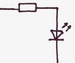 |
المقاومة على التوالي لازمة لكل تطبيق LED. A series resistor is a must for every LED application. |
وإذا أردنا استخدامه مؤشراً لتطبيق 12 V فتُحسب المقاومة على التوالي كالتالي: When we want to use this LED as a indicator for a 12 V application the series resistor has to be calculated like this:
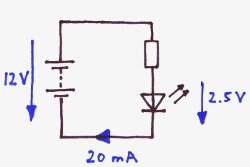 |
الجهد الكلي 12 V، والتيار واحد في كل مكان ويجب أن يكون 20 mA، والجهد على المصباح يجب أن يكون 2.5 V. The overall voltage is 12 V. The current is everywhere the same and should be 20 mA. The voltage across the LED should be 2.5 V. |
التيار معلوم: 20 mA The current is already known: 20 mA
والجهد على المقاومة يمكن حسابه: 12 V − 2.5 V → V R = 9.5 V The voltage across the resistor can be calculated: 12 V – 2.5 V VR = 9.5 V
الآن المقاومة: R = V / I → 9.5 V / 0.02 A Now the resistor: R = V / I 9.5 V / 0.02 A R = 475 ΩR = 475 Ω
وحسب سلسلة E-12 تكون المقاومة المناسبة التالية 470 Ω. According to the E-12 series the next suitable resistor has 470 Ω.
هذه الدارة الصغيرة تصلح مؤشر جهد يبين هل يوجد جهد أم لا، وهذا مفيد أحياناً في الإلكترونيات حين يُطلب الفحص لا القياس الدقيق؛ ففي الإلكترونيات الرقمية مثلاً يكفي كشف الإشارات العالية أو المنخفضة، وكثيراً ما يكون المقياس الرقمي أبطأ من تغيرات الجهد السريعة. ومصباح LED بسيط مع مقاومة على التوالي مركبين في قلم حبر قديم عون كبير للكشف عن هذه الجهود أو الإشارات. This small circuit can be used as a voltage indicator. It can show if a voltage exists or not. This is sometimes helpful in electronics when just have to be checked rather than exactly measured. In digital electronics for example high or low signals just have to be detected and a digital multimeter is often to slow for fast voltage changes. A simple LED with the series resistor mounted in an old ball pen is a great help for detecting this voltages or signals.
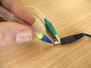 |
المصباح والمقاومة مدمجان في علبة القلم، وسنّ القلم القديم يعمل مجساً، وكبل قصير بملقطة يغلق الدارة ويُوصل بالأرضي.
The LED and the series resistor are integrated in the ball pen housing. The old ball pen tip acts as a probe and a short cable with a clamp closes the circuit and is connected to ground. |
قانون القدرة: التيار عبر مقاومة أو حمل لا يُنشئ هبوط جهد فقط بل ضياع قدرة أيضاً، وهذا الضياع حرارة؛ وكلما زاد هبوط الجهد أو التيار زادت الحرارة.
Power law
A current through a resistor or a load does not only creates a voltage drop but also power loss. This power loss is heat. The higher the voltage drop or the current the bigger the heat.المقاومة الأكبر (حجماً لا قيمة) تنقل الحرارة إلى الهواء المحيط بشكل أفضل فتسخن أقل. وضياع القدرة (الاستطاعة) يعتمد على حجم المقاومة. A bigger resistor (in size, not in value) is able to transfer heat better to the surrounding air. It gets less hot. The power dissipation (wattage) depends on the size of the resistor.
إلى جانب قيمة المقاومة يجب التأكد من أن حجمها أو استطاعتها صحيحة. Beside the resistor value we also have to make sure that the resistor size or the power rating of the resistor is correct.
في العمل يكون حساب المقاومة دائماً أمرين معاً: حساب المقاومة بقانون أوم، وحساب الاستطاعة بصيغ القدرة التالية: In practice a resistor calculation is always both: A resistance calculation according Ohm's law and a power rating calculation according the following power formulas:
| P = V × I أو P = V² / R أو P = I² × R P = V x I or P = V2 / R or P = I2 x R |
ومع الأسف لهذه الصيغ الثلاث ثلاث تنويعات لكل منها، أي يجب تعلم 9 صيغ أو معرفة أسلوب تحويل الصيغ. Unfortunately these three formulas have also three variations each. That means 9 formulas have to be learned or the technique of converting a formula has to be known.
لكن هناك حيلة صغيرة: بسبب قانون أوم يمكن التعبير عن أي قيمة ناقصة بالقيم الأخرى، أي لا نحتاج معرفة إلا صيغة قدرة واحدة: But there is a little trick. Because of Ohm's law every missing value can be expressed by the others. That means, we only have to know one power formular:
P = V × IP = V x I
فإذا كانت المقاومة معلومة والتيار غير معلوم، نحسب التيار أولاً بقانون أوم ثم نستخدم صيغة القدرة.If e.g. the resistor is given but not the current, we first calculate the current with Ohm's law and then take the power formula.
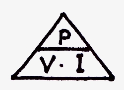 |
وهنا أيضاً يمكن استخدام هرم — مع P في الأعلى. Also here a pyramid can be used – with P in the top. |
كان التيار 20 mA والجهد على المقاومة 9.5 V. The current was 20 mA and the voltage across the resistor was 9.5 V.
فتكون استطاعة المقاومة: The power dissipation of the resistor is:
P = V × I → P = 9.5 V × 0.02 A P = V x I P = 9.5 V x 0.02 A P = 0.19 WP = 0.19 W
تكفي مقاومة عادية ¼ واط. A common ¼ W resistor can be used.
مثال 2:Example 2:مصباح 230 V باستطاعة 100 W. A light bulb for 230 V has 100 W.
فكم يبلغ التيار؟ How high is the current?
P = V × I → I = P / V → I = 100 W / 230 V P = V x I I = P / V I = 100 W / 230 V I = 0.43 AI = 0.43 A
مثال 3:Example 3:عنصر تسخين لـ 230 V ومقاومته 353 Ω. A heating element for 230 V has 353 Ω.
فما استطاعته؟ What wattage has the heating element?
P = V × I P = V x I
I غير معروف لكن يمكن حسابه: I = V / R → I = 0.65 A I is not known, but can be calculated: I = V / R I = 0.65 A
P = V × I → P = 230 V × 0.65 A P = V x I P = 230 V x 0.65 A P = 150 WP = 150 W
مشروع LED 2: وحدة تغذية مجهر تالفة ولا تُصلح، والبديل تحويل من تقنية المصباح الهالوجيني إلى منظومة LED بيضاء.
LED project 2
The power supply of a microscope is defective and can not be repaired. The alternative can be a conversion from halogen bulb technology to a white LED system.مصباح LED عالي القدرة Luxeon Star له عدسة مدمجة تركّز الشعاع بإتقان لهذا الغرض، ومواصفاته: 350 mA عند 3.42 V. A high power LED Luxeon Star has an integrated lens which focusses the light beam perfectly for this purpose. The LED has the following specifications: 350 mA at 3.42 V.
من المخطط استخدام شاحن نوكيا عادي كمصدر تغذية (5.7 V، 4 W). It is planned to use a common Nokia mobile phone charger as a power supply (5.7 V, 4 W)
السؤال: Problem:هل يصلح الشاحن؟ وما قيمة المقاومة على التوالي المطلوبة؟ Can the charger be used and what series resistor has to be taken?
1. أقصى تيار خرج للتغذية يمكن أن يكون: 1. The maximum output current of the power supply can be:
I(max) = P / U → I(max) = 4 W / 5.7 V Imax = P / U Imax = 4 W / 5.7 V I(max) = 0.7 AImax = 0.7 A
الشاحن يعطي 700 mA والمصباح يحتاج 350 mA فقط. The charger can deliver 700 mA. The LED only needs 350 mA.
نعم، يصلح الشاحن.Yes, the charger can be used.
2. لحساب قيمة المقاومة على التوالي للمصباح نحتاج الجهد عليها 2. For calculating the value of the series resistor for the LED we need the voltage across the
والتيار عبرها. resistor and the current through the resistor.
التيار معروف: 350 mA The current is already known: 350 mA
والجهد على المقاومة يمكن حسابه: 5.7 V − 3.42 V → V R = 2.28 V The voltage across the resistor can be calculated: 5.7 V – 3.42 V VR = 2.28 V
الآن المقاومة: R = V / I → 2.28 V / 0.35 A Now the resistor: R = V / I 2.28 V / 0.35 A R = 6.5 ΩR = 6.5 Ω
وحسب سلسلة E-12 تكون المقاومة التالية المناسبة 6.8 Ω.According to the E-12 series the next suitable resistor has 6.8 Ω.
3. وُجدت قيمة المقاومة، لكن هل يكفي نوع ¼ واط القياسي؟ 3. The resistor value is found, but will a standard ¼ W type be big enough?
تُحسب استطاعة المقاومة من التيار عبرها The power dissipation of the resistor is calculated by the current through the resistor
مضروباً في الجهد عليها. multiplied by the voltage across the resistor.
P = V × I → P = 2.28 V × 0.35 A P = V x I P = 2.28 V x 0.35 A P = 0.8 WP = 0.8 W
المقاومة القياسية لا تكفي، ونحتاج نوعاً بسعة 1 W.A standard resistor is NOT big enough. We need a 1 W type.
مشروع LED 3: في كثير من فحوص المجهر يلزم تخفيض سطوع الضوء، ولتخفيضه يمكن ببساطة إضافة مقاومة أخرى أو الأفضل أن نجعلها متغيرة ونستخدم مقبضاً (potentiometer).
LED project 3
For a lot of examinations with the microscope, it is necessary to reduce the brightness of the light. For reducing the light we simply can add another resistor or better we make it variable and take a potentiometer.لاحظ أننا نضيف المقبض ولا نستبدل المقاومة الموجودة؛ فلا نزال بحاجة إلى مقاومة التوالي لتحديد التيار عبر المصباح عندما يُضبط المقبض على أدنى قيمة. Please note that we add the pot and not replace the existing resistor. We still need the series resistor for limiting the current through the LED when the pot is set to the minimum
(0 Ω).
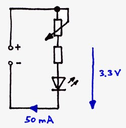 |
المقبض بالإضافة إلى تركيبة المقاومة والمصباح يخفض السطوع بتخفيض التيار عبر المصباح. A pot in addition to the resistor-LED-combination reduces the brightness by reducing the current through the LED. |
الجواب يعتمد على الجهد والتيار عند الظروف المخففة، ويجب أن نجربه. وباستخدام تغذية متغيرة ومقياس متعدد وجدنا أن مواصفات أدنى سطوع هي: The answer depends on the voltage and the current of the LED under reduced conditions. We have to test it. By taken a variable power supply and a multimeter we have found out that the specification for the lowest brightness are:
I = 50 mA عند جهد 3.3 V على المصباح والمقاومة معاً. I = 50 mA at a voltage of 3.3 V across the LED and the series resistor.
لحساب أقصى قيمة للمقبض نحتاج الجهد عليه والتيار عبره. For calculating the maximum value of the pot we need the voltage across the pot and the current through the pot.
التيار المخفض: 50 mA The reduced current is: 50 mA
الجهد على المصباح مع مقاومة التوالي: 3.3 V The voltage at the LED together with series resistor is: 3.3 V
والجهد على المقبض يمكن حسابه: 5.7 V − 3.3 V → V R = 2.4 V The voltage across the pot can be calculated: 5.7 V – 3.3 V VR = 2.4 V
الآن المقاومة: R = V / I → 2.4 V / 50 mA Now the resistor: R = V / I 2.4 V / 50 mA R = 48 ΩR = 48 Ω
وحسب الكتالوج تكون أقرب قيمة متوفرة 47 Ω.According to a catalogue the next available potentiometer has 47 Ω.
مع الأسف هذه القيمة الصغيرة ليست شائعة كثيراً وقد لا نجد مثل هذا المقبض، وربما لا حاجة لتخفيض السطوع تدريجياً؛ فربما تكفي ثلاث أو أربع درجات سطوع مختلفة، وفي هذه الحالة يكون مفتاح تدوير بمقاومات مختلفة حلاً جيداً. Unfortunately such a small value is not very common and we might not get such a pot. But maybe it is not necessary to limit the brightness continuously. Maybe three or four different brightness steps are enough. In this case a rotary switch with different resistors is a good solution.
وإذا بقي موضع فارغ يمكن استخدامه لإطفاء الضوء. If we have a position left we can even use it for switching off the light.
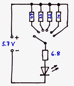 |
مفتاح تدوير بستة مواضع يعطي خمس درجات سطوع وموضع إطفاء؛ والتدوير إلى اليمين يزيد السطوع (تصغر المقاومات)، وفي اليمين تماماً لا تكون هناك مقاومة إضافية فيكون السطوع أقصى ولا يحدده إلا المقاومة 6.8 Ω. A rotary switch with 6 positions gives 5 brightness steps and an off position. Turning the switch to the right gives more brightness (the resistors get smaller). To the very right no additional resistor is in use. The brightness is maximum and just limited by the 6.8 Ω resistor. |
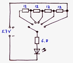 |
النتيجة هنا نفسها لكن التنفيذ مختلف: تُجمع المقاومات كلما درنا إلى اليسار. Here the result is the same but the realisation is different. The resistors are added up as far we turn to the left. |