
المكثّفات (Capacitors)Capacitors
المكثّف عنصر إلكتروني خامل يتكون أساساً من طبقتين معدنيتين متوازيتين تفصلهما مادة عازلة، وتُسمى أنواع المكثّفات باسم هذه العازلة. نستخدم مكثفات بعوازل من السيراميك والميكا والبوليستر والتنتالوم وغيرها. A capacitor is a passive electronic component which basically consist of two parallel metal layers separated by an insulator. The types of capacitors are named after this dielectric. We use capacitors with dielectrics made of ceramic, mica, polyester, tantalum etc.
تُستخدم المكثّفات لحجب الجهود أو تخزينها، ولترشيح الإشارات. Capacitors are used to block or to store voltages and to filter out signals.
للمكثّف دائماً طرفان، بعضه مستقطب وبعضه غير مستقطب. Capacitors always have two pins. Some are bi-polar others mono-polar.
المكثفات المستقطبة لها طرفان مختلفان: موجب وسالب. Mono-polar capacitors have two different leads, one positive and one negative.
|
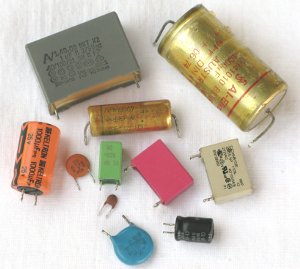
مكثفات بأشكال وأحجام مختلفة. المستقطبة عادةً أسطوانية، وغير المستقطبة قرصية أو مستطيلة.

Capacitors in different shapes and sizes. Mono-polar capacitors are usually cylindric while bipolar have disc or rectangular shape. |
الوحدات والقيم والرموز: حرف المكثّف في الصيغ هو C.
Units, values and symbols
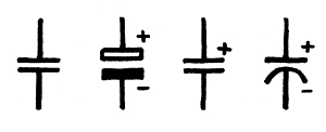
The formula letter of capacitors is C.رموز المكثفات في المخططات موضحة أدناه، وخاصة المكثفات الإلكتروليتية فلها رموز عدة مختلفة. The symbols for capacitors in circuit diagrams are shown below. Specially for electrolytic capacitors several different symbols exist.
|
مكثف غير مستقطب (يسار) وثلاثة مكثفات مستقطبة.
Non-polar capacitor (left) and three mono-polar capacitors. |
يُوصف المكثّف بسعته (capacitance) التي تُقاس بالفاراد (F). The capacitor is characterized by the capacitance, which is measured in farad (F).
وفي العمل تكون الوحدات µF وnF وpF. In practice the units are µF, nF, pF.
1,000 pF = 1 nF 1,000 pF = 1 nF
1,000 nF = 1 µF 1,000 nF = 1 µF
المكثفات غير المستقطبة: هذا النوع ليس له طرف موجب وسالب، ويمكن تركيبه في اللوح بأي اتجاه.
Non-polarized Capacitors
Capacitors of this type have no positive and negative terminal and can be mounted in both ways in the electronic board.المكثفات غير المستقطبة الشائعة مصنوعة من السيراميك أو الميكا أو البولي بروبيلين. والسيراميكية صغيرة ورخيصة وتُستخدم للتطبيقات عالية التردد. Common non-polarized capacitors are made of ceramic, mica or polypropylene. Ceramic capacitors are small, cheap and are used for high frequency applications.
الخاصية الأساسية للمكثفات غير المستقطبة أنها تحجب التيار المستمر وتُمرر المتردد، وهي أيضاً قادرة على تخزين الجهد للحظة قصيرة. The main characteristic for anon-polarized capacitors is, that they block DC and let pass AC. They are also able to store voltages for a short moment.
تُستخدم المكثفات في الإلكترونيات غالباً في تطبيقات التيار المتردد مثل مرشحات الإشارة ودارات التوقيت. Capacitors in electronics are mostly used in AC applications like signal filters and timing circuits.
وخلافاً للعازل في المكثفات المستقطبة، فإن العازل في غير المستقطبة مادة صلبة تجعل العنصر متيناً وموثوقاً؛ وأعطال هذا النوع نادرة. Unlike the dielectric in polarized capacitors, the dielectric in non-polarized capacitors is a solid material that make the device durable and reliable. Failures of this type are rare.
|
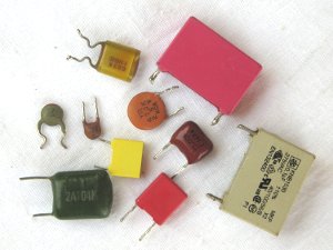
مكثفات غير مستقطبة مختلفة. الأقراص الصغيرة مكثفات سيراميكية.
Different non-polar capacitors. The small disks are ceramic capacitors. |
إلى جانب المكثفات ذات السعة الثابتة توجد أيضاً مكثفات متغيرة، لكنها ليست شائعة في أجهزة المستشفيات. Beside capacitors with fixed capacity there also exist variable capacitors. But in hospital equipment they are not common.
المكثفات المستقطبة: بعض المكثفات مثل الإلكتروليتية والتنتالوم مستقطبة، ولها طرفان مختلفان: موجب (+) وسالب (−)، أي يجب وصلها بالاتجاه الصحيح، والأطراف موسومة دائماً بوضوح.
Polarized Capacitors
Some capacitors such as electrolytic and tantalum are polarised. They have two different leads, plus (+) and minus (-). That means that they have to be connected in the correct way. The leads are always clearly marked.المكثفات المستقطبة إلكتروليتية في الغالب، والبنية أسطوانية بطرف اتصال في الطرفين (محوري — axial) للتركيب الأفقي، أو في جانب واحد (شعاعي — radial) لوضع التركيب الواقف. Polarized capacitors are mostly electrolytic capacitors. The construction is cylindric with connection lead on both ends (axial) for horizontal mounting or at one side only (radial) for standing mounting position.
وللجهود والسعات الأصغر تُستخدم غالباً مكثفات مستقطبة من التنتالوم، وهي أصغر وشكلها مختلف — شكل قطرة. For smaller voltages and capacities polarized capacitors made out of tantalum are often used. They are smaller and look different. They are drop-shaped.
المكثفات الإلكتروليتية تعطي سعة كبيرة جداً، وقيمتها دائماً بـ µF. Electrolytic capacitors offer very high capacity. The value of electrolytic capacitors is always µF.
تُوسم المكثفات الإلكتروليتية دائماً بجهد العمل الأقصى، والجهد على طرفيها يجب ألا يتجاوزه أبداً. Electrolytic capacitors are always marked with their maximum working voltage. The voltage across the terminals must never exceed this value.
وخلافاً للمكثفات غير المستقطبة فإن الإلكتروليت سائل، وهذا في العمل مصدر مشكلات كثيرة. In contrast to non-polarized capacitors the electrolyte is a liquid. In practice this fact is a source for a lot of problems.
|
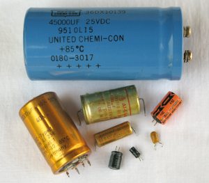
تُذكر القطبية دائماً، وغالباً يُوسم الطرف السالب (−). والمكثفات متوفرة للتركيب العمودي والأفقي؛ فالتركيب العمودي (الواقف) يسمى radial، والأفقي (المستلقي) يسمى axial.
The polarization is always mentioned. Often the negative (-) lead is marked. Capacitors are available for vertical and horizontal mounting. Vertical (or standing) mounting is also called radial. Horizontal (or laying) mounting is also called axial. |
القيم القياسية: كما في المقاومات فإن قيم المكثفات المتوفرة تُقنّن في سلاسل E، وأشهرها E-12:
Standard values
Similar to resistors the available capacitor values are standardized in the E-series. The most common series is E-12:10 12 15 18 22 27 33 39 47 56 68 82
مثال:Example:المكثفات المتوفرة هي 33 pF و220 nF و0.68 µF Available capacitors are 33 pF, 220 nF, 0.68 µF
المكثفات الإلكتروليتية لها تفاوت أعلى، وهي متوفرة بتدرج E-6 أو حتى E-3 فقط. Electrolytic capacitors have a higher tolerance. They are available only in E-6 or even E-3 graduation.
مثال:Example:10 µF، 220 µF، 4.700 µF 10 µF, 220 µF, 4.700 µF
الجهد: الخصيصة المهمة الثانية للمكثّف هي جهد الإثبات (proof voltage)، وهو أقصى جهد يمكن أن يعمل به المكثّف، وينطبق هذا خاصةً على المكثفات الإلكتروليتية.
Voltage
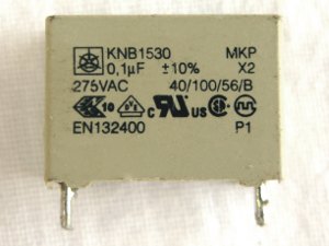
The second important characteristic of a capacitor is the proof voltage. This is the maximum voltage the capacitor can be used. This applies especially for electrolytic capacitors.المكثفات غير المستقطبة للأغراض الإلكترونية (الجهود المنخفضة) لا تُظهر جهد الإثبات في الغالب، لأن جهود الألواح الإلكترونية أصغر بكثير من جهود إثبات المكثفات؛ ولا يُلاحظ جهد الإثبات إلا في تطبيقات الشبكة (مثل 230 V). Bipolar capacitors for electronic purposes (low voltages) often do not show the proof voltage because the voltages for electronic boards are much smaller than the proof voltages of the capacitors. Only for mains application (e.g. 230 V) the proof voltage has to be noticed.
|
مكثف للشبكة. هنا جهد الإثبات مهم جداً (275 V AC).
Capacitor for mains. Here the proof voltage is very important (275 V AC) |
التفاوت: إضافةً إلى السعة وجهد الإثبات يُذكر على جسم المكثّف تفاوت القيمة، ويُدل عليه بحرف واحد:
Tolerance
In addition to the capacity and the proof voltage the tolerance of the value is mentioned on the body of the capacitor. A single letter indicates the tolerance:J ±5% · K ±10% · M ±20% J ±5% K ±10% M ±20%
مثال:Example:مكثّف مكتوب على جسمه: 105 K 330 V A capacitor which has the following text on its body: 105 K 330 V
له المواصفة التالية: has the following specification:
1 µF (الشرح في الفصل التالي)، وتفاوت ±10%، وأقصى جهد 330 V. 1 µF (explanation next chapter), tolerance of ±10%, maximum voltage of 330 V.
عادةً يكون تفاوت المكثفات الإلكتروليتية أعلى من تفاوت غير المستقطبة، وتفاوتات الإلكتروليتية غير مهمة ولذلك لا تُذكر عليها، والشائع ±20% أو أكثر. Usually the tolerance of an electrolytic capacitors is higher than the tolerance of a non-polar capacitors. Tolerances of electrolytic capacitors are not important and so they are not mentioned on the capacitors. Tolerances of ±20% or more are common.
قراءة المكثّف: إذا كنت محظوظاً تكون السعة وأقصى جهد استخدام موسومين بوضوح على المكثّف.
Capacitor Reading
If you are lucky, capacitance and maximum usage voltage are clearly marked on the capacitor.
|
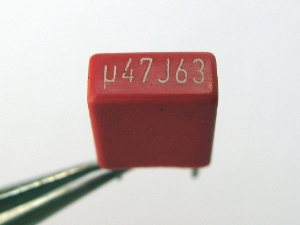
µ47 تعني 0.47 µF أو 470 nF · J تعني تفاوت 5% · 63 هي أقصى قيمة جهد استخدام بالفولت.
µ47 means 0.47 µF or 470 nF J stands for 5 % tolerance 63 is the maximum usage voltage in V |
كثيراً ما تكون قراءة القيم غير واضحة؛ فالأرقام والحروف الكثيرة تُربك. ابحث دائماً عن أرقام من القيم القياسية. Often the reading of the values is not very clear. Too many numbers and letters can confuse you. Always look for numbers from the standard values.
|
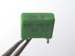
فقط الرقم 10n أعلى المكثّف يدل على السعة: 10 nF. وK تعني تفاوت 10%، و100 تعني على الأرجح جهد الإثبات. أما 1829 أو 93 أو 30 فليست أرقاماً من القيم القياسية، وقد تعني أي شيء إلا القيمة.
Only the number 10n on top of the capacitor indicates the capacity: 10 nF K stands for 10 % tolerance and the 100 probably means the proof voltage. 1829 or 93 or 30 are not numbers of the standard values. They can mean everything but not the value. |
قراءة القيمة ليست سهلة في الغالب لأن الوحدات غائبة، وبخاصة على المكثفات غير المستقطبة، ومن حيث المبدأ تعني القيمة حينها µF. The reading of the value is often not easy because the units specially on bipolar capacitors are often missing. In principle then the value means µF.
|
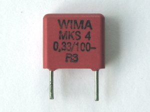
القيمة 0.33 تعني 0.33 µF أو 330 nF
The value 0.33 means 0.33 µF or 330 nF |
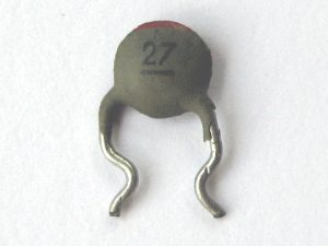
المكثفات السيراميكية (القرصية) وحدها مختلفة؛ ولأن قيمتها صغيرة جداً دائماً فإن القيمة تعني pF. Only ceramic (disk) capacitors are different. Because their value is always very small, the value now means pF.
|
مكثّف سيراميكي بلا وحدة: الرقم 27 هنا يعني 27 pF.
A ceramic capacitor without the unit. 27 in this case means 27 pF. |
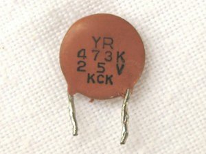
ولزيادة الإرباك يُعبَّر أحياناً عن القيمة برمز من ثلاثة أرقام، وبخاصة على المكثفات السيراميكية: الرقمان الأولان هما أساس القيمة والرقم الثالث يدل على المعامل أو ببساطة على عدد الأصفار. To make it more confusing, sometimes the value is expressed as a 3 digit number code specially on ceramic capacitors. The first two digits are the base of the value and the third number indicates the multiplier or more simply, the number of zeros.
|
مكثّف سيراميكي آخر بلا وحدة، والوحدة هنا يجب أن تكون pF. الرقم 47 يعبّر عن جزء من القيمة (سلسلة E) والرقم 3 عن عدد أصفار القيمة، فهذا المكثّف قيمته 47,000 pF أو 47 nF.
Another ceramic capacitor without the unit. Again the unit must be pF. 47 expresses a part of the value (E-series) and the 3 the number of zeros of the value. This capacitor has a value of 47,000 pF or 47 nF. |
|
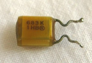
683 K تعني 68 (3× أصفار) = 68,000 pF أو 68 nF بتفاوت ±10%
683 K means 68 (3x 0) = 68 -000- pF or 68 nF with a tolerance of ±10% |
مثال:Example:102 = 10 00 = 1,000 pF أو 1 nF 102 = 10 00 = 1,000 pF or 1 nF
224 = 22 0000 = 220,000 pF أو 220 nF أو 0.22 µF 224 = 22 0000 = 220,000 pF or 220 nF or 0.22 µF
471 = 47 0 = 470 pF 471 = 47 0 = 470 pF
تمرين:Exercise:ماذا تعني الخصائص التالية للمكثفات؟ What do the following characteristics of capacitors mean?
(لرؤية الجواب مدّ المؤشّر على (To see the answer just
 المسافة خلف القيم)
the space behind the values)
104 K 50V 104 K 50V 0.1µF، ±10%، 50V0.1µF, ±10%, 50V
473 M 100V 473 M 100V 47nF، ±20%، 100V47nF, ±20%, 100V
68 K 50V 68 K 50V 68pF، ±10%، 50V68pF, ±10%, 50V
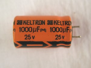
في المكثفات الإلكتروليتية الأمر أوضح: القيمة دائماً µF وتُذكر دائماً. For electrolytic capacitors it is more clearly. The value is always µF and this is also always mentioned.
والقطبية أيضاً مشار إليها دائماً بوضوح. The polarization is also always clearly indicated.
|
السعة والجهد مطبوعان بوضوح على المكثفات الإلكتروليتية: 1000 µF 25 V، والطرف (−) إلى الأسفل.
Capacity and voltage are printed clearly on electrolytic capacitors. 1000 µF 25 V (-) pin is down |
التوافيق: كما في المقاومات يمكن وصل عدة مكثفات على التوازي أو على التوالي، لكن خلافاً للمقاومات فإن السعة على التوالي تصبح
Combinations
Similar to resistors several capacitors can be connected in parallel or in series. But in contrast to resistors the capacity in series gets أصغرsmallerوعلى التوازي and in parallel أكبرbigger.
|
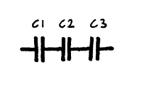
مكثفات على التوالي: تصغر السعة ويكبر جهد الإثبات.
Capacitors in series. The capacity gets smaller but the proof voltage gets bigger. 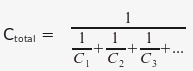
|
|
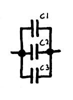
التوافيق الأشهر: مكثفات على التوازي؛ تُجمع السعات ببساطة فتكبر السعة، ويبقى جهد الإثبات كما هو.
Most common combination: Capacitors in parallel. The capacity can be simply added. The capacity gets bigger. The proof voltage remains the same. 
|
في العمل يفيد التوازي أحياناً: فالمكثّف الذي تحتاجه غير متوفر، لكن يتوفر اثنان بسعة أصغر؛ فتُجمع السعتان ببساطة، ويجب أن يكون جهد إثبات كل منهما مساوياً للجهد الأصلي أو أعلى. In practice the parallel combination is sometimes useful: The capacitor you need is not available but two of a smaller capacity. The capacities are simply added. The proof voltage of each capacitor must be as high (or higher) as the original.
مثال:Example:مطلوب مكثّف 1000 µF/25V وهو غير متوفر، لكن يتوفر مكثفان سعة كل منهما A 1000 µF/25V capacitor is needed but not available. But two capacitors of
470 µF/50V. على التوازي تصبح القيمة 940 µF أي أقل بنحو 6% 470 µF/50V are available. In parallel the value will be 940 µF which is about 6%
من الأصل. ولأن التفاوتات ±20% شائعة فإن هذا التوليف less than the original. Because tolerances of ±20% are common this combination
يمكن استخدامه، بل هو أفضل من الأصل بسبب جهد can be used. This solution is even better than the original, because of the higher
الإثبات الأعلى. proof voltage.
التطبيقات: الخصيصتان الأساسيتان للمكثفات هما تخزين الجهد والترشيح.
Applications
The two main characteristics of capacitors are storage of voltages and filtering.تطبيقات التيار المستمر — التخزين: تخزين الجهد تطبيق نمطي للتيار المستمر؛ فيُخزَّن جهد مستمر في المكثّف لبعض الوقت. ويعتمد زمن التخزين على السعة وقد يكون أجزاء من الثانية أو عدة ثوانٍ. ومن التطبيقات النمطية وحدات التغذية حيث تهدئ المكثفات جهد التيار المستمر لتبقيه مستقراً، ودارات التوقيت حيث تحدد المكثفات زمن التبديل.
DC-Applications: Storage
Storage of voltage is a typical DC-application. DC voltage is stored for some time in a capacitor. The time of storage depends on the capacity and can be milliseconds or some seconds. Typical applications are power supplies where capacitors buffer the DC voltage to keep it stable and timer circuits where capacitors determine a switching time.
|
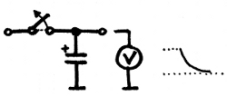
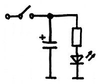
في تطبيقات تخزين الجهد يُوصل المكثّف بالأرضي (ويُرسم دائماً عمودياً)، وبعد قطع الجهد المستمر ينخفض ببطء.
For voltage storage applications the capacitor is connected to ground (drawn always vertically). After switching off the DC voltage slowly falls off. |
يعتمد زمن التخزين على السعة؛ فكلما كبرت السعة طال الزمن. وللتخزين أو التمهيد تُستخدم مكثفات إلكتروليتية مستقطبة عالية السعة. The storage time depends on the capacity. The bigger the capacity the longer the time. For storage or buffering polarized electrolytic capacitors with high capacity are used.
|
بعد قطع التغذية ينطفئ مؤشر LED ببطء؛ فكلما كبرت السعة كان الانطفاء أبطأ.
After switching off the LED slowly gets dark. The bigger the capacity the slower the time. |
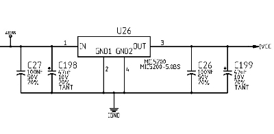
في وحدات التغذية تُستخدم مكثفات إلكتروليتية عالية السعة لتهدئة الجهد وترشيحه؛ فتنظف المكثفات جهد التيار المستمر من التذبذبات والاضطرابات. In power supplies high capacitive electrolytic are used to buffer and smooth the voltage. The capacitors clean the DC voltage from fluctuations and irregularities.
|
هذا جزء من وحدة تغذية مقياس تشبع الأكسجين (pulse oximeter). العنصر في الوسط دارة مثبت جهد، وجهد الدخل وجهد الخرج مرشّحان بالمكثفات.
This is a part of the power supply of a pulse oximeter. The device in the centre is a voltage stabilizer IC. Input voltage and output voltage are filtered by the capacitors. |
تطبيقات التيار المتردد — الترشيح: مكثّف الفصل (decoupling capacitor) مكثّف يُستخدم لفصل جزء من مرحلة إلكترونية عن آخر، وهذا مهم لأن مراحل (تناظرية) مختلفة تعمل بجهود مستمرة مختلفة ويجب فصلها من حيث التيار المستمر: يُحجب المستمر ويُمرر المتردد. فالمكثّف يرشّح الجزء المتردد من الإشارة.
AC Applications: Filtering
A decoupling capacitor is a capacitor used to separate one part of an electronic stage from another. That is important because different (analog) stages run by different DC voltages. The stages have to be separated DC- wise. DC has to be blocked but an AC signal has to pass. The capacitor filters out the AC-part of a signal.في المخططات تُرسم مكثفات الفصل أفقياً عادةً، واتجاه الإشارة من اليسار إلى اليمين (اليسار = دخل، اليمين = خرج). In schematics decoupling capacitors are usually drawn horizontal. The signal direction is from left to right (left = input, right = output).
|
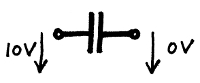
المكثّف يحجب مرور التيار المستمر؛ فالجهد المستمر على جانبه لا يولّد أي أثر مستمر على جانبه الآخر.
A capacitor blocks the flow of DC. A DC voltage on one side as no DC effect on the other side of the capacitor. |
|
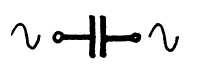
المتردد يمكن أن يمر عبر المكثّف، والضياع (مقاومة المتردد) يعتمد على السعة وتردد الإشارة المترددة.
AC can pass through a capacitor. The loss (the AC resistance) depends on the capacity and the frequency of the AC-signal. |
في الإلكترونيات يجب في كثير من الأحيان تكبير إشارات التيار المتردد (أصوات، نبضات قلب، صور فيديو...) أو تحويلها، والمراحل الإلكترونية تحتاج تغذية مستمرة للعمل؛ وأثناء العملية تتراكب الإشارة المترددة والجهد المستمر. وتلزم مكثفات لفصل المراحل من حيث المستمر ووصلها من حيث المتردد. In electronics, AC-signals (sounds, heart beats, video images...) very often have to be amplified or converted. The electronic stages need power supply (DC) for operation. During the process AC signal and DC voltage are layered. Capacitors are needed to separate the stages DC-wise and to connect the stages AC-wise.
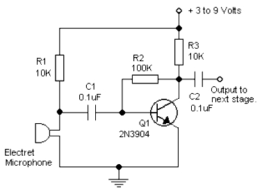
|
هذا مضخّم أوّلي (pre-amplifier) صغير؛ فالميكروفون يحتاج جهداً مستمراً معيناً وكذلك الترانزستور، ويجب فصل الجهود المستمرة وتمرير إشارة الميكروفون المترددة. المكثّف C1 يقوم بهذه المهمة، والمكثّف C2 ينقل إشارة الخرج إلى المرحلة التالية دون أي كمون مستمر؛ فالمراحل موصولة بالمتردد ومعزولة بالمستمر.
This is a small pre-amplifier. The microphone needs a certain DC voltage as well as the transistor. The DC voltages have to be decoupled but the microphone signal (AC) has to pass. C1 does this job. Also capacitor C2 leads the output signal to the next stage without any DC potential. The stages are AC-coupled and DC-isolated. |
الاختبار: مقياس السعة جهاز اختبار إلكتروني لقياس المكثفات، وكثيراً ما تتضمن المقاييس الرقمية الغالية وظيفة قياس السعات. لكن في العمل ليست وظيفة قياس السعة ضرورية فعلاً لأن أعطال المكثفات تكون مرئية عادةً.
Testing
A capacitance meter is an electronic test equipment used to measure capacitors. Upmarket digital multimeter often contain a function of measuring capacities. But in practice a capacitance measurement function is not really necessary because defectives on capacitors are usually visible.عند قياس المكثفات الإلكتروليتية تذكر أنها تعاني تفاوتات عالية. For measuring electrolytic capacitors keep in mind that they suffer from poor tolerances.
التفاوتات ±20% شائعة. Tolerances of ±20% are common.
إذا لم يكن لديك مقياس سعة فيمكن فحص وظيفة المكثفات الإلكتروليتية بوصل جهد وفصله ثم قياس الجهد المخزن بفولتميتر؛ فالجهد سينخفض بسرعة أو ببطء حسب السعة. If you do not have a capacitance meter the function of electrolytic capacitors can be checked by connecting and disconnecting a voltage and measuring the stored voltage with a voltmeter. Depending on the capacity the voltage will drop more or less quickly.
مع بعض المقاييس يمكنك تحويل المدى إلى Ω لشحن المكثّف (باستخدام البطارية الداخلية) ثم التحويل إلى مدى V لرؤية هبوط الجهد. With some multimeter you can switch on Ω range to charge the capacitor (by using the internal battery) and then switching over to the V range to see the voltage drop.
استكشاف الأعطال: معظم مشكلات المكثفات سببها المكثفات الإلكتروليتية، أما غير المستقطبة في الألواح الإلكترونية فتبقى عادةً للأبد.
Troubleshooting
Most of the troubles with capacitors are coursed by electrolytic capacitors. Bipolar capacitors in electronic boards usually last for ever.أسباب تلف المكثفات الإلكتروليتية هي التسرّبات والحرارة وسوء جودة التصنيع؛ فغالباً ما تُستخدم أجود الأنواع أرخصها بجهود إثبات قريبة جداً من جهد التشغيل، وبعد فترة من العمل على الحد تتلف المكثفات. والمكثفات الإلكتروليتية قد تسرّب أو تتشقق أو حتى تنفجر، وفي معظم الحالات يكون العطل مرئياً. ومن غير المعتاد أن تفقد المكثفات الإلكتروليتية سعتها دون أي علامة تلف. The reasons for defective electrolytic capacitors are leakages, heat and poor production quality. Very often the cheapest quality is used with proof voltages very close to the operating voltage. After some time of working on the limit the capacitors become damaged. Electrolytic capacitors can leak, crack or even explode. In most of the cases the defect is visible. It is unusual that electrolytic capacitors loose capacity without any signs of damage.
وهذا الفقد في السعة يصعب كشفه غالباً؛ فلا يكبر التيار ولا ينفصل المصهر ولا يسخن شيء، ويبدو الجهاز يعمل بشكل ما لكن ليس بشكل صحيح: الجهود غير مهدأة والإشارات غير مرشّحة وقد تظهر آثار غريبة أخرى. This loss of capacity is often difficult to discover. The current does not get bigger, fuses are not triggered and nothing gets warm. The equipment seems to work somehow but not correctly. Voltages are not buffered, signals not filtered and other strange effects can appear.
سبب الأعطال هو الإلكتروليت داخل المكثّف؛ فالمكثّف غير محكم الإغلاق في الغالب فيتسرب، وقد يتبخر السائل العازل تحت الحرارة العالية فيُحدث ضغطاً على علبة المكثّف وينتفخ أو ينفجر. Reasons for the defectives is the electrolyte inside the capacitor. Often the capacitor is not sealed perfectly and the capacitor leaks. The dielectric liquid also can vaporize under high temperature, can create a pressure on the capacitor case and makes the capacitor swell or even explode.
والإلكتروليت المتسرب قد يتسبب في تآكل اللوح المطبوع حيث يُثبَّت المكثّف؛ فابحث عن التآكل ونظف اللوح وجدد نقاط اللحام. The leaked electrolyte can also corrode the printed circuit board where the capacitor is installed. Look for corrosion, clean the board and renew the solder points.
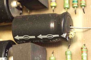
|
أعطال المكثفات الإلكتروليتية مرئية عادةً؛ هنا انفجر الجسم وخرج العازل.
Defects of electrolytic capacitors are usually visible. Here the body is burst and the dielectric comes out. |
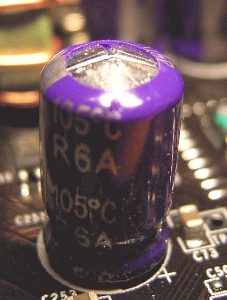
|
لمنع الانفجار يكون في المكثفات الإلكتروليتية تقويب (perforation) يسمح بخروج الغازات أو السائل العازل عند العطل.
To prevent an explosion electrolytic capacitors have a perforation to let escape gases or the dielectric liquid in case of a failure. |
عند تغيير مكثّف تذكر ما يلي: When changing a capacitor bear in mind the following:
 تأكد من صحة القطبية. Make sure that the polarity is correct.المكثفات الإلكتروليتية تخزن الجهد لفترة طويلة، ففرّغها Electrolytic capacitors store voltages for a long time.
Discharge electrolytic capacitors.
بقصر طرفيها للحظة، أما مكثفات الجهد العالي فتُفرّغ بـ by shorting the two terminal leads briefly. High voltage capacitors should be shorten by
مقاومة (مثل 1 KΩ)، وافحص الجهد بمقياسك المتعدد. a resistor (e.g. 1 KΩ). Check the voltage with your multimeter.
اختر مكثفات بجهد إثبات مساوٍ للأصلي أو أعلى. Choose capacitors with a proof voltage which is as high
or better higher than the original.الأسعار: أعطال المكثفات غير المستقطبة نادرة، فلا حاجة لتخزينها، لكن بعض المكثفات الإلكتروليتية ينبغي أن تتوفر في كل ورشة.
Prices
Defects of non-polarized capacitors are rare. There is no need having them in stock. But some electrolytic capacitors should be available in every workshop.وهذه أسعار نمطية للمكثفات في أوروبا: Here are the typical prices for capacitors in Europe:
| سيراميكيCeramic | 0.10 € |
| MKS 630VMKS 630V | 0.20 € |
| مكثّف SMDSMD capacitor | 0.30 € |
| تنتالوم 10 µF/25VTantalum 10 µF/25V | 0.30 € |
| إلكتروليتي 10 µF/40VElectrolytic 10 µF/40V | 0.20 € |
| إلكتروليتي 1,000 µF/40VElectrolytic 1,000 µF/40V | 0.80 € |
| إلكتروليتي 4,700 µF/63VElectrolytic 4,700 µF/63V | 4.00 € |
مصادر ومعلومات إضافية · المكثفات:
Sources and additional information
Capacitors: http://en.wikipedia.org/wiki/Capacitorsالأنواع: Types: http://en.wikipedia.org/wiki/Types_of_capacitor
المكثفات الإلكتروليتية: Electrolytic Capacitors: http://en.wikipedia.org/wiki/Electrolytic_capacitor
التطبيقات: Applications: http://en.wikipedia.org/wiki/Applications_of_capacitors
الأعطال: Defects: http://en.wikipedia.org/wiki/Capacitor_plague