
اصنعها بنفسكDo-it-yourself
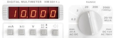
من صنع Frank Weithöner created by Frank Weithöner
مرجع جهد عالي الدقةPrecision Voltage Reference
لمعايرة المقاييس المتعددةfor Multimeter Calibration
من صنع Frank Weithöner created by Frank Weithöner
مرجع جهد عالي الدقة لمعايرة المقاييس المتعددة: أردت مؤخراً ضبط جهد نهاية الشحن في منظم شحن شمسي، ولم أوفق؛ فكل مرة أفحص فيها حالة الشحن كانت النتيجة مختلفة عن ضبطي السابق. وبعد عدة أيام اكتشفت أن المشكلة لم تكن في المنظم ولا في البطارية، بل في أنني استخدمت مقياسين مختلفين أعطيا جهدين مختلفين.
Precision voltage reference for multimeter calibration
Recently I wanted to adjust the end-of-charge voltage of a solar charge controller. I failed. Each time I checked the state of charge the result was different from my previous adjustments. After several days I found out that the problem was not the charge controller or the battery but just the fact that I used two different multimeters. The multimeters simply showed different voltages.فتساءلت، وجمعت كل مقياس متعدد استطعت الحصول عليه وطبّقت عليه جهداً ثابتاً. وهذه النتيجة: Becoming curious I collected all multimeters I could get and applied a fixed voltage to all of them. Here the result:
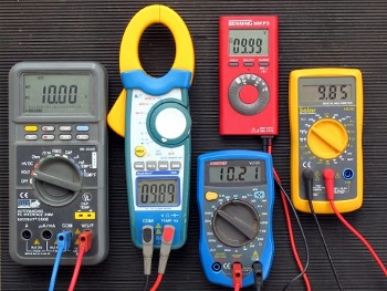 |
لا تُصدق الفروق بين المقاييس وكلها موصولة بمصدر التغذية نفسه! فمن منها يعرض الجهد الصحيح؟ وهل 10 V عندي هي فعلاً 10.00 V؟
 Unbelievable the differences between the multimeters. All are connected to the same power supply. But which one shows the right voltage? And is my 10 V really 10.00 V? |
الأمر واضح: كل المقاييس الرقمية يجب فحصها ومعايرتها إن لزم. ولهذا يلزم مرجع موثوق، إما فولتميتر معاير أو جهد مرجعي دقيق بما يكفي. والمقياس المعاير غالي أما مثبت الجهد الدقيق فليس كذلك؛ فبأقل من 10 € يمكنك بناء مصدر جهد مرجعي بدقة 0.3% أو أفضل، وهذا يطابق مستوى مقياس رقمي عادي (مثل UNI-T61A,B,C,D الشائع بدقة ±0.5%). والأفضل من ذلك أنك تحوّل مقياساً رخيصاً إلى جهاز قياس دقيق. The case is clear: All digital multimeters have to be checked and if necessary, calibrated. Therefore a reliable reference is needed, either a calibrated voltmeter or a sufficiently accurate reference voltage. A calibrated multimeter is expensive but a precision voltage stabilizer is not. For less than 10 € you can build a reference voltage source with a precision of 0.3 % or less. That correspond to the standard of a normal DMM (e.g. the popular UNI-T61A,B,C,D has ±0.5 %). And even better, you can turn a cheap multimeter into a precision measurement equipment.
المثبت الدقيق: مرجع الجهد الدقيق ليس إلا وحدة تغذية بثنائي زينر دقيق أو أفضل بمثبت جهد دقيق. وهناك مثبتات دقيقة في السوق تختلف في الدقة والسعر، وجهد خرجها غالباً 5.000 V أو 10.00 V.
Precision stabilizer
A precision voltage reference is nothing else than a power supply with a precision zener diode or better a precision voltage stabilizer. There are some precision stabilizers on the market. They all differ in accuracy and price. The output voltage is mostly 5.000 V or 10.00 V.وهذه بعض المثبتات الدقيقة (وربما يوجد غيرها): Here are some precision stabilizers (there are probably more):
| النوع Type | الخرج · الدقة · السعر · ورقة البيانات Output | Accuracy | Price | Data sheet |
| LT1431LT1431 |
5.000 V5.000 V |
0.4 % |
2.50 € |
تحميل
download |
| AD581JAD581J |
10.00 V10.00 V |
0.3 % |
9.00 € |
تحميل download |
| AD587JAD587J |
10.00 V10.00 V |
0.2 % |
5.00 € |
تحميل download |
| LM4040LM4040 |
10.00 V10.00 V |
0.1 % |
1.00 € |
تحميل download |
| LT1021CLT1021C |
10.00 V10.00 V |
0.05 % |
6.00 € |
تحميل download |
| LT1236LT1236 |
10.00 V10.00 V |
0.05 % |
7.00 € |
تحميل download |
عند اختيار المثبت انظر إلى دقة المقياس الذي تريد معايرته وإلى دقة المثبت نفسه؛ فدقة المقياس بعد معايرتك لا يمكن أن تكون أفضل من دقة المثبت. When choosing a stabilizer look at the accuracy of the multimeter you want to calibrate and at the accuracy of the stabilizer. The precision of the multimeter after your calibration can not be better than the precision of the stabilizer itself.
عيب المثبتات الدقيقة أنها قطع خاصة جداً وليست متوفرة دائماً وفي كل مكان. The disadvantage of precision stabilizer is, that they are very special parts and not always and everywhere available.
التجميع: المخطط بسيط. اخترت مثبت LT1236 لأنه كان سهل الحصول عليه. جهد الدخل غير حرج ما دام بين 15 V و30 V، والمكثفات ضد أي تذبذب. هذا كل شيء.
Assembly
The circuit diagram is simple. I have chosen a LT1236 stabilizer just because I could get it easily. The input voltage is not critical, as long it is between 15 V and 30 V. The capacitors are against any oscillating. That's it.
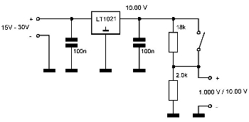 |
لا حاجة إلى لوح؛ فكل القطع مثبتة بين مقابس الخرج والمفتاح.
A board is not needed. All parts are mounted between the output sockets and the switch. |
وللحصول على جهد ثانٍ 1.000 V أضفت مقسّماً للجهد، وهو ليس أساسياً. ويجب أن تكون نسبة تركيبة المقاومات 9:1؛ اخترت 18 KΩ و2.0 KΩ، وأي تركيبة أخرى تصلح ما دام التيار لا يتجاوز التيار الأقصى للمثبت. In order to get a second voltage of 1.000 V I added a voltage divider. But that is not really essential. The value of the resistor combination has to be 9:1. I have chosen 18 KΩ and 2.0 KΩ but any other combination is fine, as long as the current does not exceed the maximum current of the stabilizer.
لكن المشكلة الأساسية هي جودة المقاومات؛ فيجب أن تكون دقيقة أيضاً. والمقاومات المعدنية العادية 1% أو 2% لا تكفي من حيث المبدأ، لكن طريقة جيدة هي انتقاء زوج من كومة مقاومات معدنية بمقياس المقاومة، بتحفّظ ونقد شديدين؛ فلا مكان للتسويات هنا. But the main problem is the quality of the resistors. They of course also have to have precision quality. Standard metal film resistors of 1 % or even 2 % are not good enough - in principle. But a good possibility is to select a pair out of a pile of metal film resistors with your ohmmeter. Be very careful and critical. Compromises here are out of place.
وهناك طريقة أخرى (وهي ما فعلته): بدل مقاومة 18 KΩ واحدة أخذت عشر مقاومات 180 KΩ على التوازي (زائد عشر مقاومات 20 KΩ). الفكرة أن التفاوت الكلي يصغر لأن التفاوتات تتعاوض كلما زاد عدد المقاومات. جرّبت الطريقة وكانت النتيجة أن كل مقاومات 1% كان تفاوتها الحقيقي 0.25% فقط لكل واحدة، وبوضعها كلها على التوازي انخفض تفاوت المقاومة الكلية إلى 0.04%. Another possibility is the following (this is what I did): Instead of taking one 18 KΩ resistor, I took 10 of 180 KΩ in parallel (plus 10 of 20 KΩ). The idea is that the overall tolerance gets smaller, because the tolerances compensate each other the more resistors are used. I tested the method and the result is the following: All 1 % resistors actually had a tolerance of only 0.25 % (each one). Putting all in parallel the tolerance of the overall resistance dropped to 0.04 %.
علبة مناسبة: لم أستطع الحصول على واحدة هنا في تنزانيا، فركّبت كل شيء داخل مقياس الورشة؛ كان هناك مكان كافٍ في الداخل وأيضاً في الواجهة للمقابس، وميزة أخرى أنني استخدمت التغذية الداخلية. A suitable enclosure I could not get here in Tanzania, so I mounted everything into my workshop multimeter. There was just enough space inside and also at the front for the sockets. An other advantage was, that I could use the internal power supply.
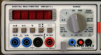 |
مصدر الجهد المرجعي مركّب داخل مقياس الورشة (المقبسان الأزرق والأسود تحت مفتاح التدوير). والمقبض الأحمر بينهما مفتاح تبديل من 10 V إلى 1 V.
The reference voltage source build in my workshop multimeter (the blue and the black socket under the rotation switch). The red knob in between is the change-over switch for 10 V to 1 V. |
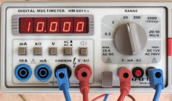 |
ممتاز: حتى بعد 15 سنة لا يزال مقياسي في حالة جيدة...
Perfect. Even after 15 years my DMM is still in a good shape... |
تحديث — النسخة الثانية: نسخة أخرى تحتوي AD581، وهذه المرة في علبة خارجية. قوابس الدخل مدمجة في العلبة بحيث يمكن وصل الجهاز مباشرة بتغذية المختبر. وللنسخة الثانية أيضاً مفتاح لتبديل جهد الخرج من 10.00 V إلى 1.00 V.
Update: Second version
Another version contains the AD581, this time in an external enclosure. The input plugs are integrated in the encosure so that the device is directly attachable to the lab power supply. Also V2 has a switch for changing the output voltage from 10.00 V to 1.00 V.
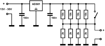 |
ولتقليل تفاوت المقاومات استخدمت هذه المرة أربع مقاومات على التوازي.
In order to reduce the tolerances of the resistors I used this time4 resistors in parallel. |
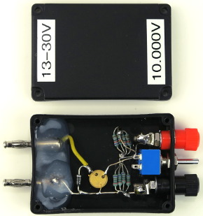 |
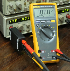 |
الآن نأتي إلى الضبط. Now we come to the adjustment.
داخل المقياس الرقمي: قلب كل المقاييس الرقمية دارة متكاملة عالية التكامل: محوّل تناظري/رقمي (A/D) مع سواقة شاشة LCD أو LED. تعالج الدارة جهداً مستمراً في مدى 0-200 mV وتعرضه، ومقسّمات جهد مختلفة يختارها مفتاح التدوير (أو تحكم آلي) توسّع هذا الميلي-فولتميتر ليصبح فولتميتراً عملياً. ونحن نتجاهل هنا محوّلات التيار والمقاومة.
Inside a DMM
The heart of all digital multimeters is a highly integrated IC, the A/D converter with the LCD or LED display driver. The IC processes and displays a DC voltage in a range of 0-200 mV. Different voltage dividers selected by the rotation switch (or by an automatic control) extend this mili-voltmeter to a practical voltmeter. The converters for currents and resistances we ignore here.وعند المعايرة نضبط فقط الجهد المرجعي لهذا المحوّل، أي مدى 200 mV؛ فمقاومات المقسّمات ثابتة ولا يمكن ضبطها، وهذا ما يسهّل العمل. When we now do our calibration we only adjust the reference voltage of this A/D converter, that means the 200 mV range. The resistors of the dividers are fixed and can not be adjusted. That makes the work easy.
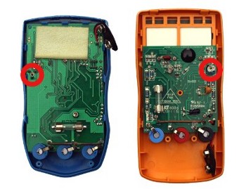
مقبض ضبط واحد فقط
Just one trimmer
 |
الأمر سهل جداً — يوجد مقبض ضبط واحد فقط. اختر مدى الجهد الذي تستخدمه أكثر (مثل 200 V)، وصل الجهد المرجعي واضبط الشاشة على 10.00 V. انتهى.
That's easy-peasy - there is only one trimmer. Switch to the voltage range you mostly use (e.g. 200 V), connect the reference voltage and set the display to 10.00 V. That's it. |
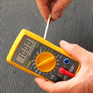 |
بذلك تصنع جهاز قياس دقيق من مقياس رخيص.
Making a precise measurement equipment out of cheap multimeter. |
كيف تجد مقبض الضبط الصحيح: الأمر سهل في المقياس البسيط لأن المقبض واحد. لكن بعض المقاييس فيها مقابض عدة، فلا تدر المقابض أبداً لتعرف أيها الصحيح؛ فستفسد مديات أوضاع أخرى مثل AC والتيار. الأفضل أن تتعرف على دارة المحوّل A/D وترجع إلى ورقة بياناتها حيث تجد موضع مقبض الضبط.
How to find the right trimmer
It is easy when you have a simple DMM. There is only one. But some multimeters have several trimmers. Please do NOT turn the trimmers to find out which is the right one. You will mess up the measurement ranges of other modes like AC or current. It is much better to identify the A/D converter and look it up in the data sheet. There you find where the adjustment trimmer is positioned.والدارة الأشهر هي ICL7106، وتأتي في علبة DIL بـ 40 طرفاً أو علبة SMD مربعة. وهناك دارة شائعة أخرى هي ES51922 المستخدمة مثلاً في طرازات UNI-T T61 الشهيرة. The most common IC is the ICL7106. The IC comes in a 40 pin DIL package or as a square SMD package. Another common IC is the ES51922 which is used for example in the popular UNI-T T61 models.
| IC | الاتصال · الطرف · ورقة البيانات Connection | Pin | Data sheet |
| ICL7106 · 40 طرفاً DILICL7106 40 pin DIL |
REF HI، REF LOREF HI, REF LO |
35, 36 |
تحميلdownload |
| ICL7106 · 44 طرفاً SMDICL7106 44 pin SMD |
REF HI، REF LOREF HI, REF LO |
43, 44 |
تحميل download |
| ES51922ES51922 |
VR، VRHVR, VRH |
37, 38 |
تحميل download |
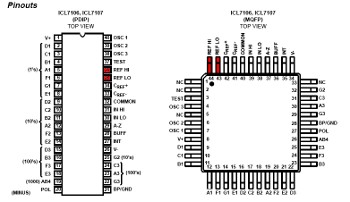 |
المتكاملة الشهيرة ICL7106. اتبع الأطراف الموسومة لتصل إلى مقبض الضبط الصحيح. تكبير
The common ICL7106. Follow the marked pins and get to the right trimmer. enlarge |
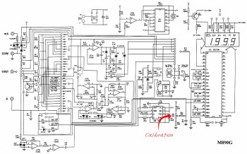 |
المقياس M-890G، مثال لمقياس يستخدم ICL7106. تكبير
The M-890G. An example for a DMM with the ICL7106. enlarge |
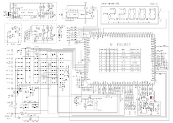 |
مخطط UNI-T T61 الشائع، ومقبض المعايرة موسوم بالأحمر. تكبير
The circuit diagram of the popular Uni-t T61. The calibration trimmer is marked red. enlarge |
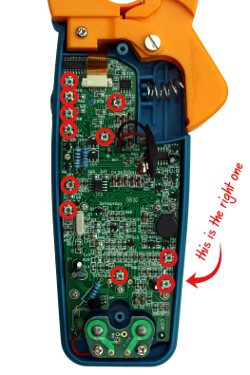 |
هذا المقياس ذو الملقط فيه مقابض كثيرة؛ تعرّف على دارة المحوّل A/D واتبع مسارات النحاس حسب ورقة البيانات، ولا تدر المقابض لتعرف الصحيح! فستشوّه الأوضاع الأخرى.
This clamp multimeter has many trimmers. Identify the A/D converter and follow the conducting tracks according data sheet. Do not turn the trimmers to find out the right one! You will distort the other modes. |
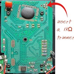 |
أرخص مقياس: هذا المقياس بخمسة يوروات من سوق محلي في قلب تنزانيا لا يمتلك مقبض ضبط أصلاً، لكن يمكن إضافته بسهولة.
The cheapest meter. This 5 €- multimeter from a local market somewhere in the heart of Tanzania has not even a trimmer. But it can be easily added. |
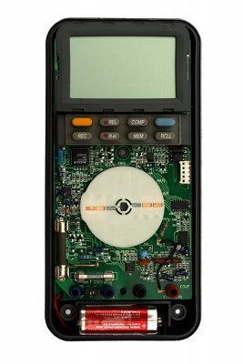 |
الاستثناء: هنا لا شيء يُضبط؛ فالمعايرة تُجرى ظاهراً ببرنامج خاص عبر منفذ البيانات (على الجانب الأيمن في الوسط)، ولحسن الحظ لم تكن هناك حاجة إلى معايرة.
The exception. Here is nothing to adjust. Obviously the calibration is done with a special software via the data port (on the right side in the centre). Fortunately there was no need for a calibration. |
ملحق: ليتني فكّرت بهذا قبل. لطالما أزعجني أن مشاريع المساعدات الإنمائية تنفق أموالاً كثيرة على أجهزة من أعلى طراز؛ فلماذا يجب أن يملك كل كهربائي FLUKE 179؟ لقد رأيت أدوات وأجهزة قياس غالية كثيرة متشققة أو متسخة جداً (أو مفقودة)، ولذلك لا أشتري أساساً إلا أجهزة رخيصة (لكن معقولة) أجدها في المحلات المحلية. وفي المستقبل سيحصل كل شخص أيضاً على مقياس متعدد رخيص مني، يعايره الفني معي؛ وهكذا يتعرّف على مقياسه أكثر ويقدّر قيمة أداته، خصوصاً حين يدرك أن مقياسه بعد ضبطه أدق على الأقل من FLUKE 179 الذي يكلف عشرة أضعافه...
Addendum
I wish I had had this idea before. It has always bothered me that for developing aid projects a lot of money is spent on top-class equipment. Why must every electrician have at least a FLUKE 179? I have seen so many expensive tools and measurement equipment which were cracked or filthy dirty (or simply have disappeared), so that I basically only buy inexpensive (but reasonable) equipment that I find in local shops. In future everybody will also get an inexpensive multimeter from me which the technician together with me will calibrate. By doing so he gets to know his DMM better and hopefully also appreciate the value of his instrument, especially when he realizes that his DMM after his tuning is at least as precise as a 10-times more expensive FLUKE 179...روابط ومصادر — للأدلة أو المخططات جرّب
Links and sources
For manuals or circuit diagrams try Workshop equipment manuals.المزيد عن More information about Multimetersفي ويكيبيديا. at wikipedia.
مصدر القطع الإلكترونية والأسعار: Source for electronic components and prices: Reichelt