
 |
اصنعها بنفسكDo-it-yourself
تحويل المجهر إلى إضاءة LEDMicroscope Conversion to LED-Light من صنع Frank Weithöner created by Frank Weithöner |
يوضح هذا الدليل كيف تُحوّل مجهراً عادياً بمصباح إلى إضاءة LED. ويكفي شاحن هاتف نقال رخيص كمصدر تغذية بسبب الاستهلاك الأقل بكثير لإضاءة LED، فلا حاجة لإصلاح وحدات التغذية الأصلية التالفة أو تبديلها؛ ولأن LED لا ينقطع لم تبق حاجة إلى المصابيح. This instruction shows how to convert a standard microscope with light bulb to LED light. Only a cheap mobile phone charge can be used as the power supply because of the much lower power consumption of the LED light. Defective original power supplies do not have to be repaired or exchanged. Because a LED does not break, light bulbs are no longer needed.
تكلفة منظومة LED كاملة أقل من 20 €. The whole LED system costs less than 20 €.
الفكرة وراء ذلكThe idea behind
كثيراً ما نصادف في ورشتنا مشكلات في وحدات تغذية المجاهر التالفة، وهي عادةً وحدات تغذية تبديلية (switch mode) لا يسهل إصلاحها. ومن البدائل تغذية المصباح من مصدر خارجي قياسي، لكن هذه المصادر التي تعطي 2 A (عند 12 V) أو حتى 4 A (عند 6 V) إما غير متوفرة أو غالية جداً، ولا تزال وظيفة التعتيم غائبة... In our workshop we often encounter problems with broken power supplies of microscopes. The power supplies are usually switch mode power supplies that can not be repaired easily. To supply the light bulb with an external standard power supply is an alternative but such power supplies which deliver 2 A (at 12 V) or even 4 A (at 6 V) are either not available or too expensive, and a dim function is still missing...
وفي حالات أخرى تكون المصابيح محترقة، وهذه المصابيح الخاصة جداً غير متوفرة غالباً. In other cases the bulbs were blown and these often very special bulbs are not available.
في الماضي كانت هذه المجاهر غير قابلة للإصلاح، أما اليوم فنحوّلها إلى إضاءة LED، وهذا يعمل بامتياز. In the past these microscopes could not be repaired. But now we convert these microscopes to LED illumination. That works perfectly.
مصابيح LED البيضاء فائقة السطوع، وبخاصة ذات العدسة، ساطعة كالمصابيح العادية 20 W لكنها تحتاج جزءاً صغيراً من التيار؛ فالتيار المطلوب صغير لدرجة أن شواحن الهواتف النقالة العادية تصلح مصدر تغذية، وهي رخيصة ومتوفرة عادةً. White ultra-bright LEDs, especially with a lens, are as bright as common 20 W-bulbs, but they only need a fraction of the current. The current needed is so small that common mobile phone chargers can be used as a power supply. Mobile phone chargers are very cheap and commonly available.
المزاياAdvantages
لتحويل الإضاءة إلى LED مزايا مهمة: The conversion to LED light brings some interesting advantages:
• الضوء ساطع جداً. • The light is very bright.
مصباح LED بقدرة 1 W مع عدسة ساطع كالمصباح العادي 20 W. A 1 W-LED in combination with a lens is as bright as a conventional 20W-light bulb.
• الضوء أبيض حقيقي. • The light is real white.
المصابيح العادية تعطي ضوءاً مائلاً إلى الصفرة يجب تصحيحه بمرشح أزرق، أما ضوء LED Light bulbs produce a yellowish light which has to corrected by a blue filter. LED light is
فأبيض حقيقي ولا يتغير لونه عند التعتيم. real white and also does not change the colour when dimming.
• LED يدوم طويلاً جداً، فلا حاجة لمصابيح احتياطية. • LEDs last for ever. No spare bulbs are needed any more.
العمر المتوقع لـ LED نحو عشرات آلاف الساعات، وهو أيضاً غير حساس The life expectancy of LEDs is about some ten thousand hours. They are also insensitive
للصدمات والاهتزازات. against shocks and vibrations.
• الاستهلاك الكهربائي أقل بكثير. • The power consumption is much lower.
الاستهلاك منخفض لدرجة أنه يمكن استخدام وحدات تغذية رخيصة. The power consumption is so low that cheap power supplies can be used.
• المجهر يعمل على البطاريات لساعات. • Microscope can run with batteries for hours.
حزمة بطاريات صغيرة (قابلة للشحن) تكفي لساعات عمل، A small (rechargeable) battery pack can provide power for some working hours.
وقد تُدمج أحياناً داخل المجهر نفسه. Sometimes the battery pack can even be integrated in the microscope.
• المجهر وLED يسخنان أقل. • Microscope and LED gets less warm.
الاستهلاك الأقل يعني حرارة أقل، فلا يسخن المجهر Less power consumption also means less heat. The microscope does not get warm any
بعد الآن. more.
• التحويل أرخص من إصلاح وحدة التغذية. • The conversion is cheaper than a repair of a power supply.
المنظومة الكاملة مع وحدة التغذية تُبنى بأقل من 20 €. The whole system with power supply can be build for less than 20 €.
العيوبDisadvantages
أعترف أن LED البيضاء عالية القدرة ليست (بعد) متوفرة في كل مكان، لكن لأن استخدامها عام ولا يكفي إلا طراز واحد لكل أنواع المجاهر (ولأغراض أخرى أيضاً) فإن من المنطقي طلب بعض القطع من أوروبا أو أمريكا. وفي أوروبا يكلف LED بقدرة 1 W مع عدسة مدمجة نحو 10 €. I admit a white high-power-LED is not (yet) available everywhere. But because they are universal in the usage and only one model fits for all microscope types (and for other purposes) it make sense to order some pieces from Europe or US. In Europe a 1 W-LED with integrated lens costs about 10 €.
اعتباراتConsiderations
بعد تجربة أنواع مختلفة من LED في مجاهر مختلفة وصلت إلى الخلاصة التالية: After testing different LED types in different microscopes I came to the following conclusion:
تتوفر مصابيح LED فائقة السطوع في علب قياسية 5 mm (رقم 1). وست إلى اثنتي عشرة LED تعطي ضوءاً ساطعاً بما يكفي (رقم 2)، لكن الإضاءة بستة مصابيح فقط قد تكون أقل تجانساً، وزاوية الشعاع ليست مثالية لكنها مقبولة. وسعر المصباح الواحد Ultra-bright LEDs are available in standard 5 mm housings (No.1). Six to twelve LEDs produce a light which is bright enough (No.2). But the illumination with just six LEDs could be more homogeneous. The beam angle is not perfect but acceptable. One LED costs
0.20 - 1 €.
إلى جانب المصابيح القياسية توجد مصابيح Luxeon عالية القدرة (رقم 3). Beside the standard LEDs there are Luxeon high power LEDs (No.3).
وتوجد أنواع 1 W و3 W وحتى 5 W، ويُثبَّت المصباح على لوح صغير بطبقة ألمنيوم تعمل مشتتاً للحرارة، وهذا يسهّل التركيب والتبريد. وزاوية الشعاع 110° ويجب استخدام بصريات إضافية. ويكلف مثل هذا المصباح 5 - 10 €. 1 W, 3 W and even 5 W-types exist. The LED is mounted on a small PCB with an aluminium board. The aluminium acts as a heat sink. This make mounting and cooling easy. The beam angle is 110°. An additional optic has to be used. Such LEDs cost 5 - 10 €.
مصباح LED واحد بقدرة 1 W (أو تركيبة تعادلها) يكفي، ويجب ألا تتجاوز زاوية الشعاع 15°، و10° مثالية. A LED (or LED combination) of one 1 W is enough. The beam angle should be no more than 15°. 10° are perfect.
أفضل حل عندي هو Luxeon Star/O (رقم 4): LED بقدرة 1 W بعدسة مدمجة 10°، وسعره نحو 10 €. For me the best solution is the Luxeon Star/O (No.4). It is a 1 W-LED with an intergrated lens of 10°. The price is about 10 €.
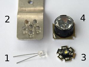 |
1 مصباح فائق السطوع في علبة 5 mm · 2 محاولة أولى بـ 6 مصابيح 5 mm · 3 Luxeon 1 W عالي القدرة · 4 Luxeon Star/O مع بصريات
1 super bright LED in standard 5 mm housing 2 first try with 6 x 5 mm LEDs 3 Luxeon 1 W high power LED 4 Luxeon Star/O with optic |
الدارة الإلكترونيةThe electronic circuit
لا يمكن وصل المصابيح مباشرة بمصدر تغذية خارجي، بل يلزم تحكم إلكتروني. The LEDs can not connected directly to an external power supply. An electronic control is needed.
يُتحكم بالمصابيح بالتيار لا بالجهد؛ فيجب أن يكون التيار مستقراً وأن يُعدَّل الجهد آلياً. ويجب أن يعمل مثبت التيار هذا مع أي شاحن هاتف عادي، أي يلزم دخل واسع المدى من 5 إلى 15 V، وأن يعطي الشاحن 400 mA وهو ما يتحقق دائماً. LEDs are controlled by the current and not by the voltage. The current has to be stable and the voltage will be adjusted automatic. This current stabilizer must run with any common mobile phone chargers. That means a wide-range voltage input of 5 - 15 V is demanded. The mobile phone charger has to deliver 400 mA which is always the case.
مواصفات مصباح Luxeon هي 350 mA عند 3.42 V، وعلى الإلكترونيات المطلوبة تثبيت تيار الخرج عند 350 mA أياً كان جهد الدخل. والدارة بسيطة لكنها دقيقة. The specifications of a Luxeon LED are: 350 mA at 3.42 V. The needed electronics has to stabilize the output current to 350 mA whatever the input voltage is. The circuit is quite simple but tricky.
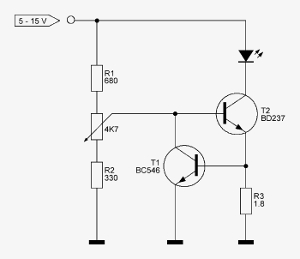 |
المخطط: الترانزستوران T1 وT2 يكونان مثبت التيار؛ ومقسّم الجهد حول مقبض الضبط يقلل انحياز T2 لتعتيم المصباح. ولأن تيار LED مثبت فإن جهد التغذية غير حرج ويمكن استخدام أي شاحن هاتف.
The circuit diagram. T1 and T2 make the current stabilizer. The voltage divider around the pot reduces the bias for T2 in order to dim the LED down. Because the LED current is stabilized the supply voltage is uncritical. Every mobile phone charger can be used. |
الترانزستور T2 يتحكم بالمصباح، وهو مع R3 على التوالي مع المصباح؛ أي إن تيار المصباح يمر أيضاً في الترانزستور والمقاومة. وعلى التوازي مع المقاومة يوجد مسار BE في الترانزستور T1، ولأن هبوط جهد BE في الترانزستور 0.7 V دائماً فإن الجهد على المقاومة مثبت أيضاً عند 0.7 V. فإذا كان الجهد على المقاومة ثابتاً والمقاومة ثابتة فسيكون التيار فيها ثابتاً أيضاً — أي إن التيار مثبت. Transistor T2 controls the LED. Together with R3 it is in series with the LED. That means that the LED current also flows through the transistor and the resistor. Parallel to the resistor is the BE path of the transistor T1. Because the BE-voltage drop of a transistor is always 0.7 V also the voltage across the resistor is fixed to 0.7 V. But when the voltage across the resistor is fixed and the resistor anyway then also the current through the resistor must be fixed. The current is stabilized.
وتعتمد قيمة التيار على المقاومة R3. The value of the current depends on resistor R3.
R3 = 0.7 V / 0.35 A → R3 = 2 Ω R3 = 0.7 V / 0.35 A R3 = 2 Ω
وبعد التجربة اخترت 1.8 Ω. After testing in practice I chose 1.8 Ω.
وضياع القدرة في المقاومة نحو 1/4 واط. The power loss of the resistor is almost 1/4 Watt.
P = 0.7 V × 0.35 A → P = 0.245 W P = 0.7 V x 0.35 A P = 0.245 W
نظرياً تكفي مقاومة 1/4 واط لكنها ستسخن؛ وبمقاومة 1/2 واط نكون في الجانب الآمن. In theory a 1/4 Watt resistor is OK but it will get hot. With a 1/2 Watt resistor we are on the safe side.
يُُنشئ مقسّم الجهد R1 ومقبض الضبط وR2 جهد الانحياز لـ T2، وقيمه غير حرجة لأن التيار محدود أصلاً. وR2 مسؤولة عن أقل سطوع وتضمن مدى تغير جيداً لمقبض الضبط. The bias voltage for T2 is created by the voltage divider R1, the pot and R2. The values are uncritical because the current is already limited. R2 is responsible for the lowest brightness and ensures that the pot has a nice variation range.
T1 ترانزستور عام منخفض القدرة من نوع BC 546 أو ما يشبهه. T1 is a universal low power transistor of type BC 546 or similar.
أما T2 فيجب أن يكون أكبر، وحجمه يعتمد على هبوط الجهد بين CE وهو الفرق بين جهد التغذية وجهد المصباح (3.42 V) وهبوط 0.7 V على R3؛ فكلما ارتفع جهد التغذية وجب أن يكون T2 أكبر. T2 must be a bigger one. The size of T2 depends on the voltage drop across CE. It is the difference between the power supply voltage and the LED voltage (3.42 V) and the 0.7 V voltage drop across R3. T2 has to be bigger, the higher the power supply voltage is.
V(CE) = V(in) − V(LED) − V(R3) V(CE) = V(in) - V(LED) - V(R3)
وضرب هبوط جهد الترانزستور V(CE) في تيار المصباح يعطي ضياع قدرة الترانزستور؛ ويجب مراعاة التيار وضياع القدرة عند اختيار نوع الترانزستور. The transistor voltage drop V(CE) multiplied by the LED current makes the transistor power loss. Current and power loss have to be considered when choosing the transistor type.
مثلاً BD 139 كبير بما يكفي؛ وقد أخذت BD 243 الأكبر فقط لأنه كان في متناول اليد. A BD 139 for example is big enough. I took the even bigger BD 243 just because it was lying around.
المشتت الحراري الصغير لا يضر أبداً، وفي هذه الحالة يكون تثبيت T2 مباشرة على هيكل المجهر أفضل فكرة: تُوصَّل الحرارة عبر الهيكل وتُثبَّت الأجزاء الأخرى على الترانزستور مباشرة، فلا حاجة إلى لوح مطبوع. A small heat sink is never wrong. In this case mounting T2 directly to the housing of the microscope is even a better idea. The heat can be conducted away over the housing and the other devices can be mounted directly to the transistor. No PC Board is needed.
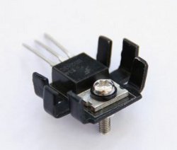 |
عند استخدام مشتت حراري أو الهيكل المعدني للمجهر تأكد من تثبيت الترانزستور معزولاً بعازل ميكا، لأن الجزء المعدني في الترانزستور موصول عادةً بالمجمع، والمجمع في دارتنا غير موصول بالأرضي — تأكد أن المسمار أيضاً معزول عن الترانزستور.
When using a heat sink or the metal housing of the microscope be sure that the transistor is mounted insulated by using a glimmer
insulator. Usually the metal part of the transistor is connected to the collector. But in our circuit the collector
is not connected to the ground. Make sure that also the screw is insulated from the transistor. |
التحضيرات الميكانيكيةMechanical preparations
لا تزال العدسة الأصلية مع علبة المصباح مطلوبة، ويُثبَّت المصباح مباشرة على اللوح السفلي؛ تأكد من وضعه بالضبط حيث كان فتيل المصباح القديم. The original lens with the lamp housing is still needed. The LED will be mounted directly on the bottom plate. Make sure that the LED is placed exactly there, where the filament of the light bulb was before.
قرص المرشح الأزرق لم يبق لازماً، ويمكن إزالته من علبة المصباح. The blue filter disk is not needed any more. It can be taken out of the lamp housing.
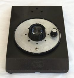 |
قاعدة المجهر بعد إزالة الحامل والآلية والبصريات. تظهر علبة العدسة مع العدسة في الوسط، وعلى اليمين مقبض التعتيم الجديد، وأسفل علبة العدسة مفتاح صغير للتشغيل/الإيقاف. وكان مقبضاً مدمجاً مع مفتاح أجمل لكنه لم يكن متوفراً.
Base of the microscope. The stand with the mechanic and the optics is removed. The lens housing with the lens is seen in the centre. At the right is the new pot for dimming and below the lens housing a small toggle switch for on/off can be seen. A combined pot/switch would be nicer but was not available. |
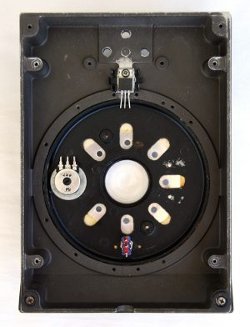 |
منظر القاعدة من الداخل: المقبض والمفتاح مركّبان لكنهما غير موصولين بعد، ووُجد مكان جيد للترانزستور في ثقب موجود بلولب. أُزيل الطلاء من سطح هيكل المجهر قبل التركيب، فأصبح للترانزستور اتصال حراري ناعم ومستوٍ.
View to the base from the inside. Pot and switch are already mounted but not wired. For the transistor a nice place was found. An existing hole with a threat could be used. The paint from the surface of the microscope housing was removed before mounting. The transistor now has a smooth and plane thermal connection. |
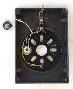 |
أصبح للمجهر مقبس تغذية في الخلف (أعلى)، والتوصيلات جاهزة، ولم يبق إلا تثبيت المصباح على اللوح السفلي. والقطع مركّبة مباشرة على الترانزستور والمقبض، فلا حاجة إلى لوح مطبوع.
The microscope gets an power supply socket at the back (up). The wiring is finished. Only the LED has to be mounted on the bottom plate. The parts are mounted directly at the transistor and at the pot. A PCB is not needed. |
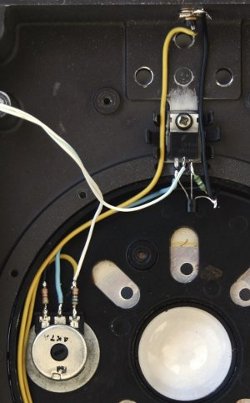 |
منظر تفصيلي للتوصيلات: تأكد من عزل T2 عن الهيكل المعدني واستخدم معجوناً حرارياً في التركيب. وبعد إنهاء الأعمال الميكانيكية لا يستغرق التوصيل أكثر من 15 دقيقة. منظر أقرب
A detailed view to the wiring. Make sure that T2 is insulated from the metal housing. Also use thermal paste for mounting. When the mechanical work is finished the wiring takes only 15 minutes. A closer look |
الخبراتExperiences
كان كل المستخدمين راضين تماماً عن التحويل، ولم أسمع شكوى واحدة من الإضاءة. ويبدو أن LED بقدرة 1 W مع عدسة تركيز يكفي فعلاً لكل الفحوص، وحتى مع عدسة الزيت 100x المستخدمة لفحص الملاريا لا يكون السطوع كافياً فقط بل أعلى من الإضاءة الأصلية. All users where very satisfied with the conversion. I never heard a complain about the light. It seems that a 1 W-LED with a focus lens is really enough for all examinations. Even with the 100x oil-objective which is used for malaria examination the brightness is not only high enough but it is even brighter than the original illumination.
| تحديث 2015
Update 2015 |
النسخة 700 mAThe 700 mA version
مرت خمس سنوات منذ كتبت المقال السابق، وفي هذه المدة أصبحت المصابيح أرخص وأقوى، فقررت ترقية إضاءة المجهر بمصباح أقوى. والنتيجة إضاءة بمصباح 700 mA أي ضعف السابق، والتغذية الآن من شاحن USB بـ 5 V. وأعرض هنا مثالاً: تحويل مجهر Olympus CH-2. Five years have passed since I wrote the above article. In the meantime the LEDs got cheaper and more powerful. So I decided to upgrade the microscope illumination with a more powerful LED. The result is a microscope illumination with a 700 mA LED, which is twice as much as before. The power supply now is a 5 V USB power supply. As an example, here the conversion of an Olympus CH-2.
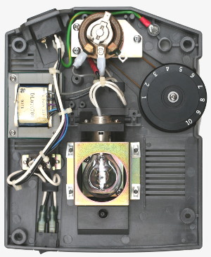 |
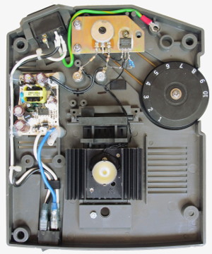 |
|
|
الفروق عن نسخة 350 mADifferences to the 350 mW version
المصباح مشابه لنسخة 1 W؛ فالجهد نفسه لكن التيار الآن 700 mA بدل 350 mA، والعدسة مطابقة أيضاً. The LED is similar to the 1 W version. The voltage is the same, but the current now is 700 mA instead of 350 mA. The lens is also identical.
مخطط مثبت التيار يبقى كما هو، ولا يتغير إلا قيمة المقاومة R3 بسبب التيار الأعلى. ويُستحسن الآن مشتت حراري لـ T2 وللمصباح. The circuit diagram of the current stabilizer remains the same. Only the value of resistor R3 has to be changed due to the higher current. Also a heat sink for T2 and the LED is advisable now.
الحساب في النسخة الجديدة سهل: جهد المصباح نفسه (≈ 3.4 V) لكن تياره ضعفان، أي إن التيار عبر T2 وR3 سيكون ضعفين أيضاً. ولأن هبوط الجهد على R3 لا يزال 0.7 V فيجب أن تكون المقاومة نصف القيمة، وهذا سهل: أخذت مقاومتين مما لدي على التوازي، فتنصف المقاومة وتتضاعف الاستطاعة وهو أمر لازم أيضاً. The calculation for the new version is easy. The LED voltage is the same (≈3.4 V) but the LED current is twice as much. That means, also the current through T2 and R3 will be two-times bigger. Because the voltage drop across R3 is still 0.7 V, the resistor itself has to be two-times smaller then. That is easy to do, I simply take two of the resistors I still have in parallel. That halves the resistance and doubles the wattage, what is also necessary.
الترانزستور BD237 كـ T2 لا يزال مناسباً (2 A) لكنني أخذت BD243 (6 A) لأن لدي منه كثيراً. وهذه المرة يجب مشتت حراري للترانزستور بالتأكيد، لأن ضياع القدرة فيه تضاعف وهو يسخن فعلاً. The BD237 as T2 is still fine (2 A) but I took a BD243 (6 A) just because I have many of them. This time the transistor definitely needs a heat sink because the power loss across the transistor is twice as much and it gets really warm.
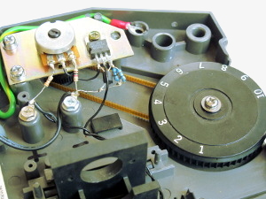 |
أُزيل المقبض السلكي (wire potentiometer) القديم ورُكّب الجديد في الموضع نفسه ليبقى القرص الأصلي صالحاً للاستخدام، فلن يشعر المستخدم بأي فرق. وتُستخدم لوحة التركيب أيضاً مشتتاً حرارياً لـ T2.
The original wire potentiometer is removed and the new one is mounted in the same place so that the original dial can be used.
The user will not feel a difference. The mounting plate is also used as a heat sink for T2. |
وينطبق هذا خاصةً على المصباح؛ فـ LED لا يسخن كالمصباح الهالوجيني لكن تبقى فيه حرارة معتبرة يجب توصيلها بعيداً. أجرِ تجربة تشغيل: إذا سخن المشتت لدرجة لا تستطيع لمسه فخذ أكبر، ولا تنسَ عزل التركيب والمعجون الحراري. This applies in particular to the LED. An LED does not get hot as a halogen bulb but still there is quite some heat that has to be conducted away. Make a test run. When the heat sink gets so hot that you can not touch it any more, take a bigger one. Do not forget the mounting insulation and thermal paste.
أخذت مشتتاً حرارياً كبيراً للترانزستور، وهو أكبر من اللازم لكنه يناسب مجهر Olympus تماماً ولم تكن هناك حاجة إلى تعديلات لاحقة لموضع المصباح. I took quite a big transistor heat sink. That is bigger than needed but in case of the Olympus it fits perfectly and later alignments of the LED were not necessary.
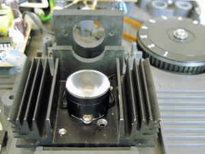 |
المصباح الجديد يحتاج مشتتاً مناسباً، ويجب أخذ قياسات ثقوب التثبيت بدقة شديدة للتأكد من أن التركيز في المنتصف فعلاً. ويمكن أن يفيدك كثيراً اختبار سطوع بسيط كما هو موصوف أدناه.
The new LED needs a proper heat sink. The measurements for the bore holes have to be made very carefully and precise in order to make sure that the focus is in really in the centre. A simple brightness test as described below can be very helpful. |
في النهاية ستأخذ على أي حال مشتتاً أو قطعة معدن تناسب مجهرك وتضع المصباح في موضعه المثالي، ولذلك ستحتاج غالباً إلى بعض الأعمال المعدنية. أجرِ تجربة بتركيب المشتت في مكانه قبل حفر ثقوب المسامير. In the end you have to take anyway a heatsink or a piece of metal which fits into your microscope and positions the LED perfectly. Therefore some metalwork will be probably necessary. Make a test with the heatsink in place before you drill the holes for the fixing screws.
وحدة التغذيةThe power supply
لإبقاء ضياع القدرة صغيراً يجب أن يكون جهد الدخل أصغر ما يمكن؛ فـ 5 V أو 6 V مثالية، وضياع القدرة صغير ولا يزال لـ T2 «هامش» للتحكم. To keep the power loss small, the input voltage has to be as small as possible. 5 V or 6 V are perfect. The power loss is small and T2 has still 'margin' to control.
الحرارة (ضياع القدرة) في T2 تعتمد على هبوط جهد CE. فمع تغذية 5 V يكون الهبوط 1.6 V فقط (5 V − 3.4 V)، وبضربه في تيار 700 mA نحصل على 1.1 واط حرارة فقط. The heat (power loss) across T2 depends on the voltage drop of CE. If we use a 5 V power supply the voltage drop is just 1.6 V (5 V-3.4 VLED). Multiplied by the current of 700 mA makes just 1.1 W of heat.
أما لو استخدمت تغذية 12 V فإن ضياع قدرة الترانزستور يرتفع إلى 9.6 واط! But if you would use a 12 V power supply the power loss of the transistor increases to 9.6 W!
هذه المرة استخدمت شاحن USB بـ 5 V وركبته داخل هيكل المجهر. This time I used a 5 V USB power supply which I installed in the microscope housing.
الاختبارTesting
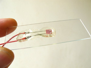 |
طريقة بسيطة لقياس تغيرات السطوع: مقام مقاومة ضوئية (LDR) ملصقة على شريحة مجهر. A simple way of measuring changes in the brightness: A LDR glued on a microscope slide. |
وأخيراً تعليق موجز على اختبار السطوع. At the end a brief comment on testing the brightness.
لا أملك جهاز قياس للسطوع، لكن لديّ مقاومة ضوئية LDR لصقتها بغراء إيبوكسي في وسط شريحة مجهر ووصلتها بأوميتر. بهذه الطريقة لا أحصل على قيمة مطلقة للسطوع، لكنني أرى التغيرات وأقارن القيم، وهذا يكفي لضبط موضع المصباح ومقارنة السطوع بمصباح المجهر الأصلي. I do not have a measurement instrument for the brightness. But what I have is a LDR which I glued with epoxy glue in the centre of a microscope slide and connected it to an ohmmeter. With this method I do not get an absolute measurement value of the brightness but I can see changes and can compare values. That is enough to align the LED and compare the brightness with the original microscope lamp.
إذاً، نتيجة قياسي غير العلمية في حالة Olympus CH-2 هي: مذهل! إنه أسطع بكثير جداً من الأصل... So, my non-scientific measurement result in case of the Olympus CH-2 is: Wow! It's much, much brighter than the original...
مصادر ومعلومات إضافيةSources and additional information
Frank's transistor data list
www.luxeonstar.com